Thursday 18 July 2019

Bicycle Dynohub maintenance and Lighting

Changed; 27/09/2024 - 25/09/2024
Sturmey-Archer hub generators, variable speed hubs (GH6, GH8, GH12, AG, FG, AW, FW) and bicycle lighting. 

Click on any diagram to see sharper images.  Some of the circuit diagrams with a few function block could be spaced out more to be less cluttered.  I have made a compromise so they can be viewed on this blog, instead of printed on paper.

Pictured; Sturmey-Archer, AG - 3-speed Dynohub, dated July 1953;  
3-speed wide variable gear hub and 6Vac, 1.8W generator, 40 spoke. 

Summary -  Mechanically the Dynohub was made like all Sturmey-Archer / Raleigh products of good quality materials, to be maintained and serviced in a straightforward way over their very long life span.   I have read that Sturmey-Archer Dynohubs were sold with a 50-year guarantee in 1950 the Raleigh guarantee was good but was beginning to be reduced in length of time at this time.  But they were not redesigned to use more powerful magnets, but stayed with the metal that was less prone to rusting until 1982 when considerably more powerful magnets had become available.  In 1982 more efficient, Dynohub and lighting was developed, prototypes sampled, but they were never sold.  Manufacture of Dynohubs by Sturmey-Archer ceased in 1984 (See Sturmey-Archer Story by Tony Hadland). 
 
Although the strategy is correct for re-magnetising a Dynohub I was unable to show for certain in this blog that I had done it.   But I have shown how to do it.

Content
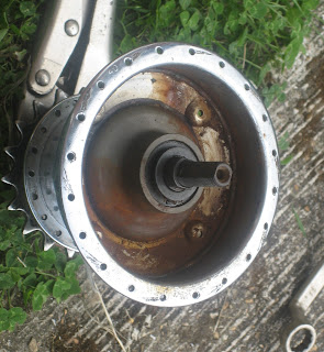
  • About the Dynohub pictured and its magnetism and efficiency. 
  • Electronics to improve the light output such as LED lighting.
  • Dynohub repair, making a magnet keeper, re-magnetising theory and practical suggestions, {in this section I have not been able to re-magnetise a dynohub for certain}
  • Newer and older 3 and 4-speed AW and FW variable gear hub lubrication and maintenance, 
  • Lighting circuits and regulator circuits, 
  • Motors that can be used as generators.
  • Addendum; Alternative LED lighting circuits that can be made from salvaged parts,
  • Addendum; Bicycle bottle generator experiments using a stepper motor salvaged from a printer,
  • Blog; Electronics project that can take more power at higher bike speed with good efficiency when required for battery charging and powering other devices.  Using a configured or learnt strategy or controlled by the cyclist.

The Dynohub pictured above;

The first impression - the sprocket turns both directions without engaging and was floppy but after dismantling, reassembling, and lubricating the gear hub is free running, it should feel loose which it does.  The case is bright chrome with some rust and the internals seen from the outside are a dirty black dry oil and dry inside.  It has not been oiled adequately probably not assembled correctly and the toggle chain is missing - this Dynohubs condition is unknown. 

The dynamo - feels dirty but does not feel like there is any internal rubbing.  Turning the dynamo is definitely lumpy, called detent force, as would be expected as the poles line up but the magnetic force is quite high - which could mean the winding is shorted and/or the magnet is in a very good state of magnetism. 

Once the terminals were tightened there was good continuity.  Shorting the contacts will make the magnet detent force stronger (harder to overcome) as should happen and indicates that the winding is not shorted.  That is as far as I can tell over the friction from internal dirt at first but now that everything is put back together properly, lubricated the hub runs fine and appears to be in good order. 

On opening the Dynohub it becomes apparent that the magnetism is not particularly strong and it is quite easy to slide the winding assembly against the magnet.  The magnet is old for the time, probably AlNiCo type that would never have been particularly strong.  The air gap, as expected, is large by modern standards of motors and generators but that is because it uses the same weight carrying bearings as the wheel this lowers the Dynohub's power a lot.  
 
It is may be that the magnet was not fully magnetised but magnetised using a calibration procedure to set the required output current.  AlNiCo has better resistance to corrosion than newer material types of the time.  If this was so then the magnet would deteriorate over time more than if it were full magnetised, which takes not just more but a lot more power to magnetise it to saturation.

Pictured above right;  Stronger ceramic/ferrite type magnet from the 1950s or early 60s TV.  And much more powerful motors using smaller air gaps, closer tolerance and much more powerful permanent magnets started to become available in about 1978.  Sturmey-Archer sampled a 3W, improved lighting set with a 30 pole and 4x improved power Dynohub in 1982 but this was not popular.  I do not know how the generator was constructed but smaller air gaps in the magnetic path would increase the output power a lot but but bearing ware would be an issue sooner.   Motor manufacturers recommend that no side-thrust be put on a motor bearing but indirect coupling be used.  A second bearing set and indirect coupling may have been Sturmey-Archer's solution also.
 

Objective;
To discuss the electrical issue with some textbook motor and generator theory.  This type of generator is the same as a single-phase permanent magnet synchronous motor.  These motors used to be used in electromechanical central heating timers.  They are also similar to a hybrid stepper motor that has; two, three, four or five phases, usually operate at low speed and are found in printers.  They are commonly used with electronic controllers everywhere from trains to wind turbines.  All so-called bicycle dynamos but have no brushes and the term is incorrect.  "Dynohub" does not appear to be a trademark but the logo would be copyright.  If the magnet is re-magnetised successfully then the Dynohub may produce a higher current at 6Vac than the rated 300mA at a lower speed. 

Graph -  current can be drawn up to the same limit irrespectively of the generator speed and then the voltage will drop sharply.  The winding's series resistance has not been included it causes the voltage to drop as the current increases.  The true output turns out to not look like this.

Small graph - With no load, the output voltage increases linearly proportionally to the speed of rotation.  A lightly loaded dynamo is the same as a tachometer and would make a good speedometer. 

In a discussion on Facebook, I have been shown the patent below which claims a method of providing some voltage regulation rather than current regulation that I suggest above - load voltage regulation is claimed.  The magnet is machined in a way to form discrete poles and gaps so presumably the magnetism does not slip around and weaken more quickly?  The claim is also that the current reaches the desired level quickly. - That would occur in any case by having a lot of poles and a high number of turns/volts coil.  The graphs with the patent do show some voltage regulation when loaded.  The description also mentions reactance of the winding being a limiting/regulating factor but I am not sure how this helps to model a generator? 

The patent is dated 1936 - I found it difficult to understand but I think the patent proposes the permanent magnet's poles be sculpted in to poles with gaps between.  {Please correct me in the comment section below}

Tests below show that the dynamo does not behave as an entirely constant current source and the voltage and current varies with speed.  Therefore this diagram shows more like the what happens. 

 
Efficiency;
The losses in the Dynohub are due to; 
  • Bearing friction which is very small in this case of a thin oiled bearing.  
  • Magnetising force - the power needed to change the magnetism polarity (north to south, south to north) in the iron conducting the magnetism to the winding this is very small and might be 1% of the power available.  That is the available power generated and the magnetising power used increases with frequency.  This can be determined by looking at the B-H curve for the mu-metal. 
  • Eddy currents in the iron conduct the changing magnetism this depends on how thinly it is laminate.  GH6 bike Dynohub's has three ply laminations there are three laminations compared to a transformer, or a motor which has many laminations.  I have read an anecdote of someone getting one or two hundred volts from a Dynohub by taking it off a bike and spinning it fast, which suggests that eddy current losses did not limit the output voltage at high frequencies and probably are not a significant issue.  That Dynohub produced 100 or 200Vac.
  • Copper losses are the losses due to the resistance of the winding (which is 5 ohms) when current is drawn is a significant factor, though not discernible by the cyclist; I2R which is; 0.45W = 0.32 x 5 in this case.  
    • This power loss is significant 25% at rated power 1.8W.
  • A different effect is observed and said on social media: a Dynohub which on small wheel bicycle's turns faster than cycling a full-size bike, and tends to burn out filament lamps, that is the output current increases with speed. 
    • A filament lamp's current self regulates a little when supplied from a voltage source such as a battery by comparison.  But the power tends to run away when supplied by a variable current source.  For example a quartz halogen filament lamp's cold resistance is about 1/20th of its hot resistance.
  • A vintage GH6, 8 or 12 Dynohub are less efficient because the magnet is lower-powered but a Dynohub uses more copper and iron in compensation but losses are still be higher. 
    • A modern hub generators losses are more than 10% of the available power when not connected but varies between makers of modern generators.  These are magnetising and eddy current losses.  The path of the alternating magnetism seems unnecessarily long.  See Skjegg blog link below for measurements carried out on some modern hub generators. 
    • See the addendum with pictures of motors at the bottom of this page for more efficient designs.  
    • But the losses are a lot higher in a modern hub generator system (up to 45%).  See Skjegg blog link below for measurements carried out on some modern hub generators.  The electronics waste power instead of using more sophistication to just take the power required.
    • The amount of power wasted in a modern hub generator additional system may be 7W compared to 2-3W below or 1W. That is if I have understood the two blogs correctly. 


Voltage regulator; 

Filament lamps are more prone to failure because a current source such as a permanent magnet generator such as the Dynohub than from a voltage source because when the current increases with bike speed the filament gets hotter its resistance increases the voltage rises more and the filament then gets even hotter.  This is called thermal run-away.
 
AL-0035-01F (4) Shunt regulator used with vintage filament lamp lighting to improve voltage regulation.  So that if one lamp fails then the other lamp will not become over-voltage and also fail.  It also prevents over-voltage and filament lamp failure at higher bicycle speeds on faster spinning small wheel bicycles.

The power wasted is up to 2W (2.5W including the Dynohub) and some of the surplus power is returned to the Dynohub as forward movement of the bicycle so that the extra effort that the cyclist puts in does not increase at high speed.  A Zener diode shunt regulator like this is not fitted as a standard and was not made by Sturmey-Archer but they can be made or purchased and added.  The switch shown is not usually fitted in that location but there is still a switch in the lamp, which it would be pointless to use because it causes dynamo power to be wasted instead of used for the lighting. 

If you disconnect the Dynohub (or a permanent magnet synchronous motor) and turn the shaft or shaft in the centre of the wheel you will feel the lumpiness of the 20 magnetic poles.  If you short the output the lumpiness increases.  The amount it springs back is the greatest with the wires shorted, that is the power taken is returned to wheel movement.  But the spring back is less when the lamps are connected because the power is absorbed by the lamps instead.  The shut regulator does not waste much more power as the bike speed increases, and the triac control the wastage is less and with my electronics project blog the wastage is less because the Dynohub is not connected too if it is not used and more power is only taken if the cyclist chooses to. 

The shut regulator only takes what is not used by the lighting.  This lighting system takes less power from the movement of the bike than modern bike dynamo systems take and the lighting is quite poor but importantly it helps the biker be seen.  Consequently, there is little surplus for battery charging or anything else.  The design project https://blog.andrew-lohmann.me.uk/2020/09/electronics-design-project-bicycle.html offers the more power optimal power transfer, to harvest more power when the bike is moving faster if the cyclist chooses to.  But you will need to do the software work (I used to find that a chore to do) and any circuit refinement you choose and worse case design. 

LED lighting;

Is more than 5 times brighter than incandescent bulbs and works efficiently over a wide bike speed range.  That is when a filament lamp is dimmed and orange an LED would still be its desired colour,  much brighter visible light. 

 
1. Simple but will flicker annoyingly.  Will run when the dynamo reaches 4V peak.  2x 1W Zener diodes protect against one of the higher power white LED going open circuit and causing other LEDs to be broken.
   The total LED current is 300 mA.

2. This will flicker much less and will run when the dynamo reaches 5V peak.  2W Zener diode, >300mA Schottky diodes.  The flicker may be acceptable without the large value capacitor.  The protective series resistor R2 is only required if C1 is fitted and the LED could be switched or connected live.
    The total LED current is 200 mA.

AL-0035-01F Unlike filament lamps LEDs work over a much wider current range efficiently without much colour change.  The Zener diodes in these circuits are protective against a white LED going open circuit and maintain some function in that case.

Where modern LED lighting may be set to use less current and a modern hub generator produce more power the circuit below takes less power from the bicycle movement. 
 
AL-0035-04E phase control voltage limited power regulator; This is a little more power efficient than the Zener clamp with low power lighting but any power saving is trivial.  But a higher voltage version is used in my electronics design project in my blog electronics-design-project-bicycle and in this case the power saving or extra the power available is significant.

Output required 5V. (4.5V to 5.5V) 

Schottky diode bridge rectifier loss; 0.8V = 0.4V x 2, to 1.0V
 
Therefore bridge rectifier input; 6.0V = 5 + 1.0V

Triac clamp;  The triac is only required to operate in 2 quadrants although the small triacs I propose are 4 quadrant mode types.  Z00607, Z01 (Z0103, Z0107, Z0109, or Z0110).

Triac gate; Vgt(maximum) = 1.3V at 25'C  
0.95Vmax at 125'C, 
Vgd = 200mV (Voltage it won't trigger at)
 
Try Zener diode PDZ3.3B (slightly over voltage), Max Vforward = 0.9V @ 10mA.

When cold the circuit is likely to output slightly over 5.5V.  This could be resolved by adding a  symmetrical FET or MOSFET type opt-isolator such as; (H11F1*) across the Zener diode pair driven from a LMV431 variable reference.
 
Required Zener diode; <3.3V = 5.5V - 1.3V - 0.9V. 
Use a 3.0V Zener instead. 
 
The lowest voltage which would occur at higher temperature than is likely is about 4.7V which although is within tolerance but many USB devices will only charge up very slowly at this voltage.   My experience with bicycle lighting is that it does still charge up at a lower voltage even though a smart device may not.
 
The indicator LED is useful but also important to ensure the bridge rectifier output does not rise to 6V with no load.

By inspection should be 4.5V to 5.5V should be met.  Which is the limit of the USB 1 or 2 output voltage but it is under powered at ~200mA whereas USB usually delivers; >500mA. 

Power not used by the lights would be wasted or returned to the dynamo in forward movement.  The extra power that was wasted by the triac (z01 ST) <600mW from a graph in the data sheet.  Compared to <2W for a Zener diode shunt regulator solution.
 
 AL-0035-01F (3) auxiliary USB power but 50% of the power is always provided for the lighting.  The regulator is similarly a more efficient shunt regulator.  The disadvantage is that there is no lights when the bike stops moving.  Thyristor type; X0202MN.
 
Thyristor or SCR are two names for the same component a silicone control rectifier but a Triac is similar to two SCRs connected anti-parallel to form a bidirectional switch.
-------------------------------------------------------------------
 

Dynohub maintenance 


Magnet keeper to prevent demagnetising - in case it is required;
The magnet will demagnetise if separated from the armature so if you remove the armature you need to replace it with a keeper such as another armature, by sliding the keeper in as you push the armature out, so that the magnetic circuit is not broken even briefly.  A magnet keeper is a piece of soft iron that conducts magnetism very efficiently with low hysteresis losses.  Mu-metal that transformers, motors, generators, and the screen on an old colour TV Cathode Ray Tube use are ideal.  You need to avoid or minimise how much the metal is worked on bent or hammer it because this hardens the metal and reduces the metal's desired magnetic conducting and flux change handling qualities.

Colour TV, Cathode Ray Tube magnetic screening is made of mu-metal.  Microwave oven transformer with high leakage inductance - pictured left.  Single-phase shaded pole induction motor - pictured right.  

Mains frequency transformers come apart into a bobbin with copper wire, and "E" and "I" section mu-metal.  The microwave oven transformer with a high leakage inductance pictured is welded and will probably be difficult to take apart, therefore look for another transformer.  The motor's mu-metal will need some more cutting to make it useful.  Very old mains and loudspeaker transformers are not varnished so come apart easily for example.  The colour TV cathode-ray-tube screen is the best source of mu-metal as can be seen in the picture. 

Making a keeper;
To cut a piece of mu-metal and carefully bend it into a radius with the ends overlapping.  It turned out the magnet is not as strong as I was expecting.  The keeper is held in place by its modest springiness.

The estimate of the dimensions from outside dimensions; 
  • BSA and others - many sizes not known. 
  • Sturmey-Archer;
    • GH12 (1937 - 44), 111 mm outside diameter (from pictures). 12V, 2.7 W, and 3 W,
    • GH8 (1939 - 44), 90 mm OD (from pictures), 8 V, 1.2 W,
    • GH6 (1944 - 83) Dynohub, AG and FG variable gear Dynohub.  6 V, 2 W (reduced to 1.8 W subsequently). 
      • The estimated magnet internal diameter measuring inside the bolts is; 70mm. and width 24 mm,
      • The length required of mu-metal required is the circumference;  210 mm = pi.D.
      • Therefore ensure there is at least 230 x 30 mm mu-metal. 
I understand that all post-world war two Sturmey-Archer Dynohubs and gear Dynohubs are the same specification and most parts are interchangeable.  The external appearance changed from time to time though.  The significant difference is that earlier hubs have 32 holes front and 40 holes rear but later hubs all have 36 spoke holes.  
 
There are other Dynohubs with fewer holes for small wheel bikes, a side effect of the smaller faster turning wheel bikes is these hubs can have a higher output power.

 
Picture - Making the keeper;  Find something of about the right diameter, (glass jar wrapped it in a rage), and then bend the mu-metal around the protected jar.  The kitchen scissors are described as cut anything up to tin plate steel and are more suitable than the tin snips on the right.  A hammer, anvil (use a vice with care), and a file to clean up the cut edges. 

I have some mu-metal and have cut a piece 30 mm x 260 mm x 0.5 mm - it looks messy because I used kitchen scissors and it would be better cut with a guillotine to make a magnet keeper for up to the largest size a GH12 hub-dynamo.  I bent the strip of mu-metal around the glass jar wrapped in a rag to form into a C shape radius with overlapping ends, and be a little larger diameter. 
----------------------------------------------------- 

The variable gear hub and other bicycle parts are made loose-fitting 
No moving parts should feel stiff or tight.  That is they tolerate grit and dirt with the minimum of harmful wear.  Traditionally frequent oiling was done to lubricate, flush out dirt and moisture.  I have been advised that oiling minimally but frequently is better and thin engine oil is good (which is what I use).

By comparison, the synchro and servo, gear-heads and tacho or Synchro resolver pictured right are expensive precision components used for measurement.  There is virtually no slack or stiffness in them.  They were supplied in the tightly fitting plastic pack shown and were made in the 1960s by Vartec.  These components can be stacked end to end and they fit firmly and easily.  Synchros and servos are used in a clean dry environment but will continue to work in a moist  environment.  The military uses them but they are rarely used in industry now. 

Synchros and servos were developed for use to compute a big gun's rang during World War 2 one of the lectures at college I attended was one of those wartime boffins who worked on gun ranging.  They do a very quick addition sum of angle inputs approximation to compute the range.  The guns is positioned to were the synchro systems produced a null I do not know if synchronous motors were used to position the gun at this time?

Disassembly of the dynamo section;
The magnet is brittle and is pressed into a soft metal enclosure that has water excluding greased lip.  There is also a waxed cardboard washer protector shown with intellectual property details printed on it.  It is not necessary to move the wiring and it is best avoided doing that unless there is an issue with continuity or insulation.  The enamel insulation on the wire will be brittle and flake off if moved if is particularly old, because enamel changed in,  I guess 1950s or during WW2 and was made of a more flexible material that could be stripped by heating rather than by scrapping. 

A dynamo hub bearings and the variable gears can be serviced without separating the magnetic parts.  In this case, the magnet moves around the winding freely and the inside looks clean enough not to require removing the armature whilst inserting the keeper.  Although the amount of cleaning possible or necessary is limited. 

I have used a mole wrench to hold the shaft by the not threaded flat sides, a 15 mm ring spanner for the nuts on the shaft, and a 5 mm nut-spinner for the 8 BA nuts that hold the dynamo section together (the 5 mm sockets I have are too fat so I needed to buy another) but what I had would have fitted a different hub.  The magnet has 20 poles in this picture. 

I have wiped to clean the surfaces then rubbed the surfaces with grease.  I have also pushed the coil a little way out of the magnet it moves too easily it should be difficult to move, indicating that the magnet has weakened over time.  But turns out that the output current is about right so the magnet is okay. 

The bearing can be seen the adjustment can be made from inside or also the adjustment can be made with the dynamo section assembled using the remote adjuster picture on the bottom left corner of the tray of parts.  I recommend that the variable gear section be opened and checked, but if you are not going to touch the variable gear section, ensure that this bearing is adjusted correctly.

If the hub does not have an oil port then the bearings do need to be greased.  This Dynohub does not require greasing and this internal bearing water-repelling labyrinth, the only greased part, is between the stationary connection plate and the moving section.  In this case, oil can get to all bearings and other parts. 
------------------------------------------------------

Inspecting the variable gear section bearings, greasing the water-repelling seals and adjusting; 
Note that the GH6 front wheel fitted type hub dynamo bearing adjustment is carried out from the non-dynamo side.  See; Sturmey Archer Front Wheel Dynohub Overhaul (60+ years old)


Video shows AW hub disassembly and that the drive side bearing is set to 1/4 to 1/2 turn slack and the non-drive side is set after the drive side bearing to 1/2 turn of slack.  There are some differences and I have shown a tray of parts for the dynohub with the dynamo side bearing disassembled. 

One difference with the variable gears only hub is that there is no press-fitting bearing oil trap so that a little lubrication from the variable gear will spread into the dynamo section.  The rust seen in the picture is a little greasy.   The hub should not be greased other than a little to hold the balls in place so that the bearing can be assembled.  This is a little different to the advice given in many videos.

The outer bearings have a grease-filled grove to repel water that grove needs any hard old grease to be scraped out and new grease packed into it.  These water barriers are the only parts that should be greased in a variable gear Dynohub.  There is water-repelling greased grove (labyrinth) between the stationary connections plate and the rotating hub, this is instead of one on the bearing that side.  The large bearing in the variable gear-hub has a little oil running out taking dirt and moisture with it.

Note; It turns out that variable gear is complete and disassembly and assembly is straightforward.  Do use the video or other sources for maintenance information.  You should not need to disassemble as far as the video shows you but also look at the planetary gears for timing marks an AG or AW does not have them but some variable gear hubs do and they must all be aligned when you re-assemble the hub. 
 
Where a gear hub does have timing marks to align on the planet gears instead of aligning them to all face out an alternative strategy is to align them to all face the same way for example clockwise use the edge of the planet assembly as a guide.  Either way they end pointing 90' to each other, ↑ → ↓ ←

-----------------------------------------------------------------------------------------


Hercules Balmoral 1975 AW variable gear hub, by comparison with a Dynohub; 
  • Put grease in the labyrinth's grove around the bearing to form a water seal, I have put the grease in the nut but not in the bearing side yet. 
  • Hold the shaft still in a vice lightly but firmly on the flat sides of the shaft, set the slack in the bearing by tightening the cone-nut finger tight then loosen 1/2 turn.  Then tighten the locknut whilst holding the cone-nut still with the thin spanner. 
  • A thin spanner is need to hold the thin inner nut whilst the outer lock nut is tightened.
This 1975 AW was in sound order internally but leaked rusty oil after oiling and riding when I first got the bike. 

Another AW dated 1985 did not run or change speed smoothly until it had been oiled regularly for a year or so.  During that time black muck came out of the hub.  When I opened the hub two years later the hub was clean inside but there was a detached pawl spring (high-speed freewheel), I made another with some success from a strand of brake cable but it is better to buy another spring.

In conclusion, the gear hub needs oiling and you can not over oil it because the oil will come out of the larger bearing carrying water and dirt with it.  The inside is not bathed in oil consequently.  Older hubs oiler port do not have a sealed cap or have no cap so excess oil would also overflow out so keeping the transmission as light as possible by using enough but not an excessive amount of oil.


Sturmey-Archer AW variable gear hub made after 1989 with no oil port.  Lubricating; (I have not carried out this maintenance procedure myself) 

A thin grease is used and every moving part of the hub must be disassembled and all moving surfaces greased.  The hub will not work if a thicker grease is used because the pawl springs are very light and the pawls will stick.
  • There is a Sturmey-Archer grease that can be obtained from SJS cycles.
  • Millers semi-fluid EP bearing grease is the correct product for hubs after 1989.  It is identical to the Sturmey-Archer product but a lot cheaper.
  • Castrol Spheerol L/EP0 is also a thinner grease that is suitable.
The no oil-port type hubs are the same internally, but the grease used is thin enough not to cause any problems.  They never need replenishing because modern grease is very good.  Despite the statement about the grease the hub was greatly improved by adding some thin engine oil after 25 years and probably should be lubricated with a little thin engine oil once a year but doing that less often works well. 
 
Do not use 3-in-one oil in a gear
hub it leaves a black residue that
stops the hub working eventually.
This hub a 1997 AW is fitted to my La-Riveria, Universal Step-thru bike and has been running very nicely operating particularly smoothly, after its initial poor operation for its first 1KM and cable adjustment when I first got the bike for 3-4 years.  The smaller pedal drop when changing speed is also much nicer than a much older gear hub. 
 
The gear are the nicest AW I have come across no doubt because most of the gear cable run is unsheathed, in the same way you find on bikes made before 1960? 


Alternatively; 
But if you've cleaned the hub out, you should put the hub back together and before you set the left-hand cone, squirt in some thin oil.  Engine oil is fine, just a quick squirt is enough. 
Use grease as normal in the outside circular groove in the cone dust caps. 
 
It has also been suggested that unscrewing the toggle chain and putting a little oil in to the hub that way will work.  I have not done that but I think you need to put more oil in because some is likely to run back out that way. 


Condition of variable gear hubs;
In three cases of a variable gear hub being out of use for many years possibly a decade or more in each case, the pawls had not stuck but in a 4th case, a spring had broken. 
 
Hardly used heavy 1955 Raleigh with a new condition FG, 4 speed, Dyno-four and
selector. 

The FW or FG four speed wide hub 
The FW is a delightful hub when it works on a traditional post war long wheelbase steel frame bike where the spacing and placing of the speeds is just right with N or three being the most efficient direct drive speed when you notice on a very good frame and benefit the most.  The reputation for the hub becoming unreliable after modest use is justified.  A 1950 FW and selector is fitted to my 1946 Lenton Sports.
  • 1950 FW the wheel turned freely and three of the four gears worked there is a fault in the hub, cable and trigger design but the hub had been properly oiled with thin oil regularly when in use since new more than 25 years earlier.  This hub had been oiled for its first 25 years with the wrong oil, 3-in-one, that had caused a fault after 30 years or so of a lot of use but the hub was otherwise clean inside. 
  • As if the hub were designed for a stiffer cable run.  The cable is very tight in Bottom gear both the cable where it had rusted on the pulley wheel and the indicator rod have broken in the past.  Evidently the cable had required progressively more tension as the deposit from the 3 in one oil deposit built up. 
  • The sheath end filed flat
    Originally the Normal gear clicked no doubt had been set that way to bring the selector positions closer together in the lighter cable tension higher gears?  My father said it was a shame because Normal is the best gear, which I agree it is being the lightest most efficient speed to pedal when it is most noticeable when you want to relax at the top of a hill or on the near flat.
  • The hub gear and selector are a 1950 made but unusually like a 1946 version the hub is a stainless steel type.  The clicking was resolved when the hub was maintained in about 2019, some pawl springs were replaced but the worn pawls and right cup which no doubt had similar wear as the pawls were kept as they were within tolerance.  I understand a lighter spring was also fitted because the original was heavy.  The hub, selector and the rear wheel rim, look like they have been replaced in 1950 under guarantee?  The hub gear is considerably better than it had been and worked properly for a short time then reverts 3 of speeds working.  Quickly the new cable deteriorated to become no better than the previous replacement.
  • The sheath end filed flat
    The cable sheath is a square section spiral so it is not compressible and a second replacement of 2024 is the same.  I do not know recall what the cable sheath from 1950 was like but it was good and the cable was plastic covered.  Drop handlebars on my bike cause the cable routing to be very curvy.  Significantly the cable shape changes as the cable tension changes but the either pieces of tape shown made all four speeds work briefly in other words gear selection is still unreliable.
  • The trigger is not worn enough to explain the issue and the notches are precise, not worn to radiuses.  Four-speed triggers are often replaced but I have not done that.  But I have damaged it a bit as a teenager but now have to squeeze the side back together with a vice successfully. 
    Tape minimise cable movement helped briefly
  • It turns out that the section of cable with an outer sheath should be no more than 18" this forms tight curves on my drop-handlebar bike.  I am not convinced that this was necessary but I have reduced the cable sheath length by 10".  I have also recently changed the outer sheath again (2024) this made the gears work properly briefly.  The bike shop did not know what a less springy type sheath recommended was and both sheaths look good tightly would square section wire? 
  • This issue with the cable shape changing at different speed selection does not arise with comparatively straight handle bars.  But all FW variable gear hubs are said to be unreliable except when they are new.  The new one on the 1955 Step-thru bike I have works very nicely, with good margin for mis-adjustment, (more than the FW on my Lenton pictured even when just set for B or just N gear but not both).  The tape to the handlebars works well then it does not work. 
But a new condition FG or FW hub, selector and cable can tolerate more than 1 mm of cable out of adjustment but a worn set which has by pulling the cable hard in Normal less than 0.5 mm of slack and perhaps does not hold all 4 speeds. In other words you really can't get all speeds and not expect the adjustment to change on a hot or cold day and at least one speed to slip causing more wear.
  • Tape minimise cable movement removed subsequently.
    Chose to set the cable to the indicator to get speeds 2,3,4. Or tighten the cable to get speeds 1,2,4.  The much greater pull effort required to get bottom gear means that the cable assembly must not be too springy which is unavoidable where the radius are severe with drop handlebars.  If a pannier bag carries much weight knocks the cable it will knock the hub out of N (3) gear.  You may have just two good speeds 2 and 4.  I have changed the rack and given the cable more clearance consequently and anyway the old new 1970s rack was welded steel which the joints kept fracturing on.
  • The correct Sturmey-Archer cables outer sheath is smaller in diameter but thicker square section spiral than brake cable and has a strong plastic outer.  The cut ends should be filed or ground flat.
  • This has improved the function and I now have 4 speeds or 3 of 4 speeds and sometimes 4 speeds but the cable needs to be adjusted often.  But the maintenance work carried out for me on the hub has made its function much better than it had been for a many decades plus the N gear does not click (not the freewheel tick) that had existed since the hub was new, and my father complained was a shame because it is the best gear.  As this is a late, early-type FW or an early later type FW the click in N probably was, a back of a fag packet, work-around, an undocumented modification. 
The FW probably did at least the average 30,000 miles between 1946 and 1950 when the FW was replaced and a lot less than the average between 1950 and 1975 when the cable broke and the hub stopped working well.  The wear shows on the small sprocket and chain stretch and might be equal to at least 100,000 miles (talking to retired bike dealers on social media) or more likely a lot of hard hills which I know my father did.
Worn sprocket from my Lenton Sports
the teeth have worn hook shaped.
I don't really know the mileage of my Lenton Sport but I do know the front bearings were worn enough to be nearly worn out (causing tight spots with 1/4 turn of slack but okay at the maximum 1/2 turn of slack) which happens at about 50,000 miles.  The chain stretched beyond when it should have occurred which would be well over 100,000 miles or a lot of heavy hill work which I know my father did with the bike and he was very fit when he completed his national service, he told me he could not sit.  Consequently the rear sprocket was worn and replaced.

FG or FW gear hub - Another solution;

Modify the hub to use a second cable.  I am advised improves the reliability of the hub and makes gear change easier is to convert it to a two cable, five-speed hub.  I have not carried out this modification to the hub;

    • In conclusion, the FW is such a nice hub with gears spaced just right with N being the most efficient perfectly placed when you get to the top of a hill, level out, speed up and need a rest.  Bottom gear is hard to get into though and on a hill by the time I have pulled the lever to B the bike may have stopped moving.  The hub along with a very good sports frame and very low friction thin oil lubrication is worth keeping and running.

---------------------------------

  • Conclusion variable gear hub maintenance;
The three speed AW gear hubs always work.

Thin-oil is spread well around the hub then leaves the hub by the bearings mostly the large planet carrier bearing then oil leaves the hub and falls onto the bicycle chain.  Thicker oils or thin grease tend not to spread around the hub and leave the hub.  

Modern engine or gear oil is designed to stick to surfaces and not run off even when a car engine is hot.  Mineral lubricants don't deteriorate over time as they used to 50 years ago or more when all car bearings were lubricated annually and engine oil changed twice a year or 3,000 miles. 

Thank you to a number of people who have advised me in various Facebook bicycle groups. 


Older and non-AW type variable speed hubs
  • Some of these have more than one lubrication point.
  • FM, FC, AM and AC are more complicated and have two epicyclic gear assemblies were developed in about 1939 to 1945. 
  • The four speed FW and FG wide spacing hubs are not so widely spaced were the last Raleigh Sturmey-Archer designed as a family owned business.
  • The AW was developed in about 1935, but newer ones have a shorter pedal drop when changing gear and from the late 1980s is sealed with a very thin grease. 
FW broken Indicator rod and Toggle chain
Picture right; Broken old type indicator rod and toggle chain from an FW (or FG) variable gear hub.  The indicator rod will fly out if you simply unscrew the toggle chain on the hub made up until the 1950s or 1960s.  On such an older hub with an indicator rod, unscrew the indicator rod so that the toggle chain on the other side can slide out. 
 
Put the wheel back adjust the chain, tighten everything then put the toggle chains and indicator rod back ensuing it is aligned properly when you tighten it but with light tension because they do break.

There is one spacer between the drive sprocket and the variable gear but the video above shows two spacers and it is important to put them back as they were found.   The sprocket needed to be put back the other way like the video and another bike that I have.  In conclusion, if this dynamo were to be used on another bike the location of the spacer or spacers would need to be reviewed. 

I was able to test the function of the variable gear by screwing an old thread type thin 1.5 mm spoke into the toggle chain place and see that the variable gear operates properly.  The 3-speed Dynohub's gears have not been road-tested on a bicycle.

---------------------------------------------------------------------------------------------------------

Magnet keeper;
You can push the keeper or another armature, as a keeper, in from one side and thereby push the existing winding out the other side for inspection and cleaning.  See TEST 4 below if you need to take this step which shows a procedure and measured outcome. 

I have been told by one person who did not have a keeper and separated the magnets to clean it then put it back successfully.  But do not do that, there is no easy way of re-magnetising the magnet.
-----------------------------------------------------

Testing the dynamo;
 1. With the bike wheel off the ground so that it can be spun freely; 
  • GH 12 - I believe the circuit is two filament lamps in series rated at 250 mA.  Short one lamp to see if the other lamp illuminates then short the other lamp this will determine if there is a simple lamp failure. 
  • GH 8  - I believe the circuit is two filament lamps in series rated at 150 mA.  If the circuit is the same as the GH 12 then the test is the same. 
  • GH 6 - The circuit is two 6V filament lamps in parallel rated to add up to 280 mA or 300 mA for example 40 mA and 240 mA.  If one lamp fails then the other lamp will be supplied with too much current and fail.  Therefore, turn the wheel slowly at first to see if one or both lamps illuminate. 
  • All dyno-hub types operate silently but the freewheel and some gear hub should tick in some speeds. 
2. With the wheel removed from the bike, the hub is set up and lubricated if necessary so that it runs freely;
  • Turn the shaft and notice the Dynamo's detent force - which feels springy sort of lumpy and is very light.  It does not matter which direction the wheel is rotated in.  The magnet is magnetised.
  • Short the dynamo output with a wire.  Turn the shaft and notice the dynamo stronger magnet detent force - which feels springy lumpy but takes more effort.   The magnet is magnetised and the windings are good so the dynamo is good
  • If the force was no different as described the winding probably has a short circuit or the connection is open circuit. 
  • Check the continuity with a battery and a light bulb or a multimeter.
  • If there was no detent force felt then the magnet is demagnetised.

If there is doubt about the lamp and the dynamo circuits test the lamp circuit with a battery instead of the dynamo.  Of cause, you can test with a multimeter rather than traditional methods but a multimeter in its time such as an AVO would cost nearly as much as a new bike in the 1930s.  The current from a battery and lamp continuity tester connected to the dynamo will cause a small high voltage spark when you disconnect it is called back-EMF which you will feel if you bridge the gap with your finger. 
 
The moving iron test meter pictured right is probably 100 years old and had cotton covered wire with a small probe tip.  It works AC or DC but the scale does not say which it is calibrated in and it is probably not accurate enough to matter.  Notice that the body of the meter is live, I have not carried out any measurements with this meter.  It would have been much less costly than a multimeter but it was not a cheap instrument. 
---------------------------------------
 
The second tool re-magnetising the magnet; 
This is the same process that happens with a computer hard disk.  A high pulse of magnetism is applied to the hard iron material to magnetise it.  Such a pulse will also switch a magnets polarity north and south poles. This is done with the dynamo fully maintained and assembled then briefly connecting a high voltage direct current power source with a circuit breaker or fuse and protection diode to the Dynohub output.

Providing that the mu-metal can carry this amount of magnetism without saturating - which is very likely because motors and generators are usually assembled then magnetised after assembly in this way. 

There is a risk that the high voltage applied to the dynamo winding will cause the insulation to break down.  The winding needs to be dry but the insulation may have deteriorated over time so applying a high voltage to the winding may cause it to fail.

I have not carried out this procedure at high voltage consequently but I have tried the procedure at a lower voltage inconclusively and have suggested a method below.  It is most likely that the insulation will withstand high voltage if it is dry and has not disturbed but the very old enamel on the copper wire is brittle and flakes off if the wire is moved.  Enamelled copper wire in anything made after about 1950 is much better and retains flexibility and the insulation is made with one of a range of high temperature plastics rather than a glass based enamel. 

AL-0030-02B S1 is closed briefly then opened to re-magnetise the dynamo. When S1 is closed the current starts to rise in the dynamo winding represented by L1, 5.5H (measured and calculated roughly) and R1, 5Ω (measured).  D1 prevents the circuit from creating a high voltage (back EMF), arcing which will hurt you and damage the dynamo's insulation.

RED = Volts GREEN = Amps.  The Ground symbol shown is not earth but is a reference point for this SiMetrix simulation.  

20A pulse shown is probably the current required to fully magnetise the dynamo (guessing based on patent detail above and the B-H curves below).  It is necessary to re-magnetise the Dynohub with the lowest possible voltage because of the age of its insulation it needs to be clean and dry, but without causing undue heating due to the longer time required to attain a high enough current.  On the other hand the voltage applied should be the highest possible so that the current pulse is short and the heating be minimal.  Therefore just enough current be applied to magnetise the Dynohub to the maximum.  Expect the Dynohubs output to be a higher current than rated or at least before the exercise was carried out.  These magnets have a wide tolerance in magnetic strength consequently the increase in the dynamo's output may vary.  The winding current must be less than the fuse rating of the wire but I do not know what the thickness of the wire is?

Assume that thinned copper wire fuse rating is similar to enamelled copper wire used in the Dynohub;
 
Estimate; 
    Winding bobbin ID; 42mm, OD; 58mm, Width; 13mm = 18mm-5mm, Winding fill factor; 75%.
    Cross-sectional Area; 156mm2 = (42-58) * 13mm * 75%
    Mean length; 157mm = Ï€ * (42 + 58) / 2 [Ï€ × mean diameter]
    Resistance of one turn of copper wire; 12.7uΩ, 
    Multiplier for; 628.5 = √(5Ω / 12.7E-6Ω),
    Wire; 628.5 turns of 0.25mm2 = 156mm2 / 628.5, diameter; 0.5mm. 
    Length; 98674.5 = 628.5 * 157mm.
 
For a GH6 dynamo,  a short pulse of current up to 20A probably won't 
cause the winding to break open-circuit. 

Diagram right;  AL-0030-01C  but at 350Vdc, 20A is attained in 0.4 Seconds and less heating. But more of the self-heating occurs after the current is turned off (the area under the curve is larger).  This can be reduced by fitting a ~10R power resistor or a surge suppressor in series with the diode. 

Include a quick blow fuse in the circuit before the rectifier in case any part breaks down, for safety, may also save the Dynohub from damage.  Progressively increasing the voltage or the fuse rating up to 5A or 10A (will break in 0.5 seconds at 3-4 times its rated current) until the dynamo's magnet has become stronger.  It is likely that a suitable high-power bridge rectifier will be found in an old washing machine. 

A rectified mains supply is more practical.  The simulation AL-0030-03C (Right and Below) - the rectified AC component in the red supply voltage pulse.  230VAC with rectifier 0.7 Seconds to reach 20A. 

The simulation is similar to the battery charger circuit below but operating from 230VAC with no transformer.  A fuse - switch - circuit breaker - and a mains voltage high current bridge rectifier need to be added but the ammeter and capacitor are not included. 

I HAVE NOT CARRIED OUT THIS PROCEDURE AT MAINS VOLTAGE AND I DO NOT INTEND TO.   IT IS DANGEROUS EVEN THOUGH I RECOMMEND USING A CIRCUIT BREAKER TO LIMIT THE CURRENT QUICKLY SO PROTECT THE DYNAMO.  I ALSO RECOMMEND AN EARTH LEAKAGE CIRCUIT BREAKER (ELCB OR RCD) FOR SAFETY. 
I did not want to damage a good Dynohub.

Ensure that the armature can move freely the poles will then align ready for the pulse of current to re-magnetise or realign the poles as the current builds up then re-magnetise the magnet.  You can test the magnetism by turning the armature if it feels lumpier the strength of the magnet has been increased successfully.  This detent force should be much higher if you short circuit the output to confirm that the winding is not a short circuit or open circuit as a consequence of re-magnetising the magnet. 

It will be necessary to experiment to find out how much is just enough current so thereby minimise the risk of damaging the Dynohub? 

It would be better to use a variable current power supply so that the magnetism can be steadily increased in steps of pulse, rest to cool, then test until the Dynohub produces the correct current.   That is the magnet is used in the linear region in a similar way that sound is recorded on tape by a tape recorder.  This would avoid putting a higher voltage than necessary across the coil.   This is unlikely to be practical without using a Variac so the magnet will be magnetised to saturation and the Dynohubs output power may be higher than 300mA. 


Alternatively use a car battery charger;
The car battery charger is connected to the dynamo, the dynamo shaft can move freely so that the magnet poles align when the pulse of power (magnetism) is applied.
  • Another strategy, is to allow the poles to move so they are aligned then hold the shaft firmly so it does not move when the pulse of current arrives but the magnetic poles may swap polarity instead.
  • Pulse the Dynohub twice so the dynamo has no cause to move again for the second pulse.  This is the most promising strategy.
The next step is as before switched on for one or two seconds then switch off.  Take care to switch off quickly so that the dynamo winding does not heat up.  Do not disconnect the dynamo whilst the power is switched on because a high voltage, called back-EMF, will be generated that will put the winding under stress unnecessarily.  See diagram below; 
AL-0031-02C (1) The car battery charger has an internal rectifier diode so another diode is not required.  Connect up then switch on for 10 seconds or so then turn off.  The low or high charge switch should be set high and the capacitor included if you have one for maximum re-magnetisation.
It turns out that it takes a few seconds for the current to build up before the shaft with the power winding aligns then re-magnetises. 

What happens; The armature (generator winding) of the dynamo (generator) will move and the magnet poles (field) and armature segments will align or re-align as the current and the magnetism increases.  This demonstration probably will not re-magnetise the Dynohub but will show how the Dynohub could be re-magnetised with a different circuit from a much higher voltage.

 
Video - Car battery charger used to re-magnetise the Dynohub.  
Ensure that the dynamo can move freely so that the poles can align.  A moving needle multimeter or a filament bulb (2.2V 470mA pictured) does a good job of measuring the function of the dynamos.  Look at the colour of the light to gauge current.  The old capacitors are similarly rated 30V to 63V 2,000uF to 5,600uF and the larger one is older.  

A digital multimeter does work if you keep the hub turning steadily for a longer period and turn off the auto-range feature.  A moving coil (needle) type multimeter works better giving a steadier reading.  The bulb lights up white indicating that the current was 470mA as the light bulb is rated and works particularly well because current is drawn so the connections are good.

It would appear that although the magnet seems weak judging by how much mu-metal sticks to the magnet but this type of hard iron magnet was going out of fashion in the 1950s and TV manufactures were using stronger ceramic magnets which are black rather than silver.  Holding the shaft in a vice - wrapping string around the housing and pulling voltage and current measurements are difficult to make. 

I measured up to 400mA short circuit with a digital multimeter, although the dynamo is only rated at 300mA.  The current may have risen to 480mA after re-magnetising.  Measuring the open-circuit voltage with a moving needle multimeter was a little easier at up to 12V increased to 20V after re magnetising.  Adding the capacitor to the circuit doubled the current in the dynamo winding but did not, as far as I can tell, increase the power output of the Dynohub after a re-magnetising again.

Warning this method was too imprecise to be conclusive.  But the method is correct even though the voltage may not have been high enough.  Adding the capacitor doubled the current to show 50%, but testing the dynamo showed no further increase in the current output subsequently.  This could be the dynamo is fully re-magnetised or not enough current was applied to change the amount of magnetism.


Tests 1;  With the dynamo clamped by the shaft with a vice and string wrapped around the hub body then pulled;

                 Open circuit V, Short circuit I, 12V 6W Lamp
Slow;       <10Vac,                440mA,               <4V
Fast;          20Vac,                 470mA                ~6V
Very fast;  30Vac,                 500mA,               8-10V

The dynamo's output is as originally expected nearly constant current regardless of speed and an open-circuit voltage proportional to the speed of rotation.  It is evident that the Dynohub operates at a minimal level and the output characteristic very curved rather than what was expected and the current is higher under short circuit condition.
 
Repeating the point the measurement is very imprecise and would be greatly improved if the dynamo were rotated at a steady speed and for longer.


Test 2;  Reverse the polarity of the magnet
  •  Connect up as above and pulse the power on/off so that the poles align*.*
  •  Reverse the polarity of the power supply.
  •  Clamp the Dynohub stationery then power on/off.
  •  Un-clamp the Dynohub so that it can move freely then power on/off.
  •   If the magnet polarity had changed the dynamo should not move but it did move to a new alignment. 
  • I also tried with a 20V DC power supply unsuccessfully. 

The battery charger probably does not provide adequate power to reverse magnetise the dynamo but it has increased the magnetism of the Dynohub.  The circuit may be useful.

1. The magnet is not fully saturated and therefore a little more power could be obtained from the dynamo.   It is likely that a much higher voltage source would cause the magnet to be greater strength than it was originally and the magnet magnetised to saturation and also take longer before it noticeably starts to deteriorate.  Magnetism is more stable when it is in the saturation region of the material.

2.  Because the magnet could not be reversed it is also likely that a dynamo that is completely demagnetised would not be re-magnetised without the need to use a much higher voltage to cause a shorter higher current pulse.  And consequently it is very likely that the Dynohubs power has not been improved?


Test 3; Demagnetise the dynamo so that magnetising the dynamo test can
be repeated.
  • Connected a 35VAC to the dynamo  - this was not adequate and the dynamo remained magnetised but the magnetism was reduced.  But the current would be quite low and the amount of demagnetisation expected would be modest.
  • The current output but showed the current was reduced to; 380-400mA after the demagnetising experiment.  Then re-magnetising and increased to 400-440mA subsequently. 
This test failed to demagnetise the magnet.  I am not willing to use a higher voltage.

WARNING - Test 1 suggests that the dynamo's current output will be higher than initially rated, remain the same after three days, and are unlikely to diminish over time.  The dynamo needs to be de-magnetised then re-magnetised but at a lower amount of magnetism.  Alternatively left as it is with higher power output.


Test 4; Replacing the winding with the magnet keeper

Pushing the keeper in and whilst pressing the keeper into the magnet to ensure the magnet has minimal gaps and the magnet path is as good as possible.


Winding removed - the fingers of the iron are tapered at the furthest tips of the soft iron fingers.
  • The keeper has been made long enough to be used on larger diameter GH8 or GH12 dynamos.
  • Once the Dynohub was re-assembled the power output proved to be not compromised by having been disassembled and the keeper used.
  • Testing the output voltage peaked at 30 Vac as before and the short circuit current varied between 370 mA to 420 mA slow to fast.
  • The tapered fingers of the coil iron as the magnetic flux lessens would not be done to save materials cost.  I can not see a voltage regulation strategy in this design.  Any power saving would be trivial due to magnetising loss being reduced by using less iron.
The assembly did not need cleaning but I did rub the parts with a little grease.  I am advised that the gaps between the magnet poles can be cleaned with a pipe cleaner.
 
 
Test 5 - repeat tests after at least 1 month since re-magnetising the dynamo
 
Slow; Vac open >17V (analogue),  Iac 370 mA (digital)
Fast;  Vac open >25V (analogue),  Iac 390 mA (digital)
 
The digital multi-meter, as before, gave less reliable readings.  I also measure the average current with the moving needle multi-meter and a bridge rectifier and this gave a consistent 300 mA fast or slow.  The true value; 330 mA (RMS) the meter is 40 years old out of calibration and the needle did not have a long enough period of current flow to settle at a final value.

    Ipk = Iav / 0.637
    Irms = Ipk x 0.707 
    Irms = Iav x 0.707/0.637 
    _330mA _= 300 x 1.11  -  Warning although the analogue multi-meter gives consistent results it most certainly is under reading and the current is higher.

Using a light bulb 2.2V 470 mA and 12V 6W I perceive that the dynamo power has diminished a little.  The multi-meters tests suggest reduced by 5-10%.  The moving needle multi-meter did not fully settle because I was not able to keep the dynamo turning long enough but it gives the most consistent results.


Conclusion - re-magnetising and electrical;
The magnet material has a tolerance but evidently, the magnet was not originally magnetised to its saturation but even so, still has very good retention of magnetism.  With readily available fixed voltage second-hand equipment power supplies it is only possible to re-magnetise a dynamo to give maximum output of about 400mA AC in this case.  After re-magnetising a Dynohub but continuing with filament bulbs then fitting one of the voltage regulators on this blog would be a good precaution in the event that the output voltage becomes higher than it would have been originally.

These tests have not proven that the current used to re-magnetise the magnet in these experiments was high enough to do that.  I did not want to demagnetise the Dynohub that I have to test this though.

My guess is that a fixed current is used to partially magnetise the magnet to achieve a 300 mA dynamo output current.  The correct current is likely found and set for each batch of magnets. 

The point about magnetising to saturation is so that the magnet would be as strong as possible but the material used has a broad tolerance.  This tolerance would have made the output power vary between batches of Dynohubs made.  Much more power is required to magnetise the magnet to saturation, but the effort required to demagnetise the magnet is also much more.  

Older style block power supplies have very loose regulation, so it should be possible to wire a number in parallel to achieve the desired current rating.  Because of their loose regulation, the current would be shared fairly equally. 
 
Alternatively older laptop power supplies are higher power 19V 4A would be suitable some are over 6A, but these do not share and you can't put two in parallel or series and parallel.

Pictured right; Old heavy transformer type block power supplies.  These range from 12V, 1A to 1.5A so two in parallel may be enough to re-magnetise a dynamo.  Four in parallel, in series with another four in parallel increase the amount of re-magnetising current.  That is 12V, 2-3A or 24V 4-6A.  Ensure that all are plugged into a gang of sockets then the mains supply to the gang of sockets is switched on briefly then off.  That is so that all the power supplies are switched on and off together. 
AL-0031-02C (2) High Voltage re-magnetising circuit.  There is a risk that the coil will brake down and be of no use.  The capacitor should be 400V or 450V and the diodes at least 600V e.g. 1N4005.
This circuit has not been made and used.  A meter should be used at each stage to check the capacitor is charged or discharged.
  • Power disconnected, The capacitor is discharged - The device to be magnetised is connected.
  • Power is connected and the switch moved to Charge - check with a meter that the capacitor is charged.
  • Switch is moved fire and check the capacitor is Fully discharged - then disconnect the power.
  • Disconnect the device.
    The device can then be checked that it has magnetised.
---------------------------------------------------------------------------------------

Rectifier regulator and LED lighting;
You can scavenge for rectifier diodes from an old PC power supply on the low voltage side diodes are usually more efficient lower voltage drop Schottky types.  Schottky diodes have a low reverse voltage rating of 20V or higher but some newer types are rated at over 100V this means that a low reverse voltage rectifier could be destroyed by the Dynohub at speed if the lamp units are disconnected. 

It is very likely that many working LEDs and optics could be recovered from a broken car headlight, side and tail light units - generally if one LED fails, open circuit, then the whole unit turns off and a dashboard warning is shown as a legal requirement in order to avoid ambiguity.  These units operate from 5V to 24V and will withstand 60V.  LEDs operate efficiently over a wide current range but their colour may change outside the road-car legal red, amber, or white.  The intensity is of each colour is also defined law as is the intensity of the stop or tail light functions. 

The red LED colour is controlled by the current fixed and the intensity stop or tail light function is changed by pulse width modulation.  PWM may operate at 100Hz, on at 100% for the stop function or for 10% of the period, for the tail light function.  Some LED types are specified to retain their colour over a wide current range and some batches of LEDs colour are stable over a range of current anyway.
 
Dynamometer tests (http://minisystem.blogspot.com/2011/11/) on a GH6 dynamo show, the Dynohub's output reached 6V 300mA at 30KPH below this speed, that blog's LED lighting drew progressively less current.  For a 26' wheel that covers about 2M per revolution the output frequency would be 83Hz which would not produce any noticeable flicker whereas 50Hz is noticeable. 
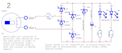
  • Therefore half-wave rectifier circuits (1 above) and (3 below) but without capacitors will noticeably flicker at 15KPH (41Hz).
  • The full-wave rectifier circuit (2 above) without the capacitors fitted may not noticeably flicker at 7KPH (41Hz).  The time that the rectified AC cycle is not carrying current is much shorter. 
Capacitor values are estimated based on simulation for <30% current ripple in the LED at a frequency of 20Hz.  Arbitrary White LED was chosen and scaled for RED LED in the LTspice simulation AL-0037-???. 
 
You could use two half-wave rectifiers which would tolerate one side short circuited See AL-0035-01E (3)
 but this does not provide much benefit the USB power supply below is better allowing you to use USB LED lighting and keeping the batteries charged. 

 
USB power 
 
These circuits have virtually no losses when no power is being taken but waste power when power is used.  Depending on how they are used the shunt regulators further above can be a  less wasteful when most of the power available is used for lighting or USB power. 

The regulator turns on after a short variable delay.  The regulator turns off when input voltage drops below the output voltage and a very capacitor is used to smooth the output voltage.  The circuit is phase control regulator that relies on the input voltage being Alternating Current.

Minimum operating voltage; >6.0V - 6.5V peak or about >4 or 4.5V rms
 
  • Assume that a GH6 hub will provide 6Vac 300 mA with a particularly strong magnet and close air gap, at 5RPM.
  • No load output voltage due to winding resistance is; 1.5V = 5R * 300 mA therefore 7.5V 
  • At 300mA the peak current 420mA.
  • Peak voltage; 10.5V = 1.4 * 7.5V , if this occurs no load at 5MPH (guess) then the maximum speed for <180V would be; 85MPH.
  • <<80MPH or <<40MPH with a small wheel bike.  These speeds or over voltage is unlikely to occur but the circuits include a Zener diode in case the dynamo is shorted than disconnected at peak current. 
 

AL-0056-01B The phase control regulator above does not waste significant power when no power is taken but relies on using high voltage thyristors and diodes so the over voltage protection is modest.

  • IC Controllers are now obsolete; TCA-785 Infineon but old stock is available.
  • A discrete solution using transistors works well.  I have created a draft design using an MIC1555 timer IC rather than a unijunction transistor such as 2N6027 and 2N6028. 
  • The losses due to voltage drop are about 1.6V which is about; 500mW.  So it is not efficient but it good enough to not take a noticeable amount of power.  It does not take any power when the lights are turned of. 
  • The controller sheet AL-0056-03? further below used with this circuit also consumes some power. 

  AL-0056-02B High voltage MOSFET switch with consequently lower voltage drop and lower power simple over voltage protection.  Phase controlled using the Alternating Voltage to switch the transistor off and recharge the boost gate driver.


  • The Controller is simple, the MOSFET + 2x Schottky diodes drop is lower than the SCR alternatives further above.
  • The controller is low speed which is okay because operating frequency is low so the switching losses should be modest. 
  • The losses due to voltage drop could be; ~1.2V which is; ~350mW (300mA * 1.2V).  But the MOSFET used is likely to have greater on resistance depending on the Dynohubs peak voltage.  And could be less efficient unless a very high current or more sensitive gate part is used?
  • At modest load the power supply turns off during part of the alternating current cycle and no power is wasted during that part of the cycle.  Overall increased power wasted is progressively reduced.

These circuits are better than the simpler triac based regulator but are not very different to each other.  This circuit could be made more efficient by reducing the maximum voltage to 100V.  The lower voltage components would tend to have lower on voltage drop's thereby making the design more efficient. 

Diode; VSSC520S-M3 200V 5A run at 0.5A will drop 0.5V, 
    PMEG10010ELXE-Q 100V 1A run at 0.5A will drop 0.5V, 

Alternative or more efficient logic level transistors; 
 FDMS86252L 12A, 150V, 75mR
 FQD7N20L 800mR 200V
 FQD12N20L 320mR 200V
 STD5N20LT 700mR 200V
 FDD10N20LZ 360mR 200V

Alternative active diode rectifier using an IC or circuit would reduce the total voltage drop to 150mV, in other words virtually nothing.  Note TEA2208T is unsuitable because it requires 15V to 22V before it starts up, But TEA1993TS works from 4V to 120V.

It probably turns out that 150V maximum is a better option giving a bicycle speed of <60MPH. 


AL-0056-03B Phase Controlled regulator for Thyristor or MOSFET power stage.
 
The SCR requires a fast pulse and the MOSFET requires a fast high impedance drive.  Both are catered for with capacitor coupling shown in each of the alternative power stages. 
 
A less efficient older version will do the job satisfactorily.  The poorer efficiency because it uses a slightly cheaper shunt regulator for the controller circuit would only be significant at high bicycle speeds such as going down hill when there would be plenty of power to waste in braking.  Old shut regulator version AL-0056-03A 
 
The power taken is about 1mA which would be 100mW at 100V or 40MPH in other words trivial.  The older circuit would take 350mW at 100V, 1.5W at 180V.
 
 AL-0056-04A Extravagant complexity for a trivial improvement in efficiency, synchronous rectifier sheet of this circuit.  Would be improved further by using MOSFET types; FDMS86252L 12A, 150V, 75mR, or FQD12N20L 320mR 200V.
 
I do not recommend these last circuits but they are developed well enough to finish off and design a PCB for.  The high side rectifier circuit is an off data-sheet variation using the lower operating frequency to hopefully allow the circuit to work with a series resistor but this variation has not been modelled or prototyped.  If the modification were to not work then the circuit could still be used but at up to 100V with components downsized if you wish.

Picture right; TEA1993TS efficient rectifier controller IC and MOSFET.  Standard circuit from the data-sheet.  Is a better option than this simpler LT4320, 9 to 72V.
 
DC-DC converters & LED drivers;
 
I CAN NOT RECOMMEND THESE SOLUTIONS BECAUSE I DO NOT KNOW AND IN ANY CASE CAN NOT MEASURE THE LIGHT OUTPUT FROM LED LIGHTING.  OTHER THAN TO SAY THE TAIL LIGHT MUST NOT BE SO BRIGHT THAT IT LOOKS LIKE A STOP LIGHT. 

Picture right;  Surface mount LEDs - A Printed Circuit Board can be made with a footprint pattern like the reverse side but as if you were looking through the parts from the top.   Design the board with components on one side only.  Place very barely a smear dot of solder paste onto the pads (it should look as if you have not got enough solder paste on the pads).  Then place the LEDs and other parts on the PCB you don't need to fit all parts at the same time or be overly careful to align them properly surface tension will cause the parts to pull to align (or miss-align).  Place the circuit board on a suitably pre-heated hotplate to solder all the parts.  Using tweezers to correct any parts that go out of alignment or tombstone (stand up).  Use pliers to remove the board from the heat without jarring it.  The board will go brown because it has been overheated and for too long but your circuit will function fine - heating and cooling need to be done quickly.  You may add solder to pads for parts not fitted and heat the board again to solder those. 
 
If you really want to fit parts both sides then after fitting most on one side using the hot plate then use a soldering iron I find best or a heat gun to solder other parts one at a time the other side or to tidy up. 

No PCB needs to be designed and ordered if you unsolder the parts off of an old circuit board, cut the tracks as necessary and place your desired circuit and wires this works well. Alternatively, you can buy some strip-board or Vero board and do a similar thing with that but you probably will need to reduce the power rating of some parts such as LEDs in order to prevent them from overheating due to the lack of solder pad, copper area for heat-sinking.

Picture right - Strip-board or Veroboard can be used for prototyping of finished one-off design.  The prototype may be a mains power supply with switch-mode or with sensitive signals?  This type of prototyping can be good to see how a function works but usually, the function does not work so well unless you think a lot about interaction of parts and signals.  The point is not to look tidy but can look cluttered but be electrically very tidy.

Alternative - Bicycle dynamo light and battery manager  ---  See Addendum at the bottom of the page and also see; Electronics-design-project-bicycle
----------------------------

Links and references; 
Tests of modern Hub dynamo efficiency; 

A method of overhauling the Dynohub that I used;

Sturmey-Archer - Dynohub history

GH12 (1936-38) - Dynohub, 12V, 2.7W and 3W

GH8 (1938-41) - Dynohub, 8V, 1.2W
 
GH6, Dynohub, AG and FG variable gear hub-dynamos. 6V, 2W and 1.8W

Tony Hadland - How to repair old Sturmey-Archer hubs
Ratios of various gear hubs
 
Note that the GH6 front wheel fitted type hub dynamo bearing adjustment is 
carried out from the non-dynamo side.  Unlike the AG variable gear dyno-hub. 

Magnet and magnetic material characteristic B-H curve https://www.quora.com/What-is-a-magnetization-curve   B = Magnetic force and H = Amp turns the current in the wire and the number of turns of wire if there were no losses in the magnetic circuit.  https://www.coolmagnetman.com/magfund07.htm
 
AlNiCo Magnet (aluminium, nickel, cobalt) material B-H curve shows the magnet can be magnetised at a lower degree of magnetism.


At very high temperatures, the material will de-magnetise called the curie point.  When the material cools again the magnetism can return.  
 

History of modern magnetic material;
 
Another bicycle dynamo project I am unsure about the data and the project was not completed but there is a useful dynamometer graph for a Dynohub;

I do not know anything about this company but they do offer a re-magnetising service.  They do magnetos which is what a Dynohub is but they are busy and it would probably be easier and cheaper to swap the inside from one hub to another.  The Magneto Guys - Vintage, Veteran, Classic Magneto and Dynamo Repairs;  https://www.themagnetoguys.co.uk/
---------------------------------------------------------------------------------

Appendix; Motors that will also generate power; 
  
  • 1970's Impex 350mA, 5V/winding (4), 48 step stepper motor.  8 wires.  
This would be suitable for a bottle dynamo project.
 
  • 1950s Induction motor (variable reluctance motor) - is not magnetised but will magnetise when connected to an AC power and spinning.  The capacitor provides a phase-shifted supply and sets the motor direction.  When spun a little faster than synchronising speed, this motor will become a generator and put power back into the supply.  
If disconnected the motor stops generating power safely.  But if capacitors are connected across the windings and the rotor has remnant magnetism some of these motors will build up magnetism and start to generate power when spinning.

This would not be suitable as a bicycle dynamo.

  • Permanent magnet brush motor - will produce direct current if spun.
This would produce direct current if spun very fast but inefficiently because of the high gearing required.
  • 1980's Astrosyn stepper motor; 24-step, 16V, 80ohms (200mA)/winding (4) - this has a much more powerful magnet than the 1970s Impex motor and is a more powerful motor it is smaller. 
This motor would make a good bicycle bottle generator see the examples further below.
  • Central heating timer permanent magnet motor - this is like the dynamo in construction but turned inside out.
This is too small to make enough power unless rotated very fast.
  • Hard disk stepper motor 8 pole - this will also generate but the voltage is so low that it would have no use.

Picture right of a high number of steps, stepper motor. The shaft is mild steel and can bend easily so the coupling to the shaft must be flexible.  The construction is different from the dynamo with the two rotors are North and South poles of a central magnet so that the teeth then present alternate poles as the rotor turns.

The motor is assembled then the magnet is magnetised by a pulse from a high voltage source.  This type of construction is used from 24 up to 500 step hybrid stepper motors.

The generator
A hub generator would be improved if it were a two-phase (4-wire) or three-phase (3-wire) the extra wiring cost is mitigated by integrating the rectifier, over voltage protection and power management plus speed output into the generator.  But the single-phase generator was the most cost-effective and a good solution in the 1930s to the 1990s that has set the standard for voltage output.

3-phase only requires one extra wire.  The 3 wires fed to a full-wave rectifier would cause a ripple in an LED would only be 15% (https://electronicscoach.com/3-phase-rectifier.html) that would not be discernable to the eye.  

All losses may be reduced if a design based on a good quality stepper motor turn inside out with say three, four or a multiple of that central windings plus a flexible coupled no side-thrust carrying bearings so that the air gap can be reduced and saving copper or copper losses all from an established motor may have improved on.  See pictures of a motor above these that can have a large hollow shaft so possibly be fitted inside a large bicycle hub over the shaft?  Such a design can be drawn up in a mechanical CAD and with the correct modelling add-ons accurately modelled.
 
Hub motors and generators;
An electric car would save 20% losses due to the transmission and gearing.  See https://youtu.be/AIvFA6YMlms?si=IGkfWYz45m-dFohS
 
-----------------------------------------------------------------------------------------------------------------------------

Appendix; Bicycle dynamo lights and battery manager;

Micro-controller-based bicycle dynamo light and battery manager with a speedometer.  Design idea and exercise with STM32 micro-controller.  With interface by USB cable for speedometer display on a tablet for example. 
  • The Dynohub should output up to 20V when the bike is ridden fast I understand.  That is up to 7W.
  • Manage battery charging.  
  • A tilt sensor is used to reduce the power taken from the dynamo using parameters set by the cyclist such as a tablet computer connected. 
More electronics design variants in detail see;

This would be a costly design to develop and a high value to sell.

No recommendation but here is a link to a generator-powered bicycle light.  A reservoir capacitor can be seen inside to smooth fluctuations but I do not know how well it shares power if two lights are fitted?;

----------------------------------------------------------

Appendix; Experimental Bicycle bottle generator lighting 

Astrosyn stepper motor; 24-step, 16V, 80ohms (200mA)/winding (4) - in experiments produces 4x  >35Vac at 25mAac.  The motor makes a good bicycle bottle generator although the sleeve bearings will wear out sooner than a ball bearing type motor.  By nature of its cheaper construction, having a longer magnetic path and less segmentation, be less efficient. 
 
I have glued a wooden wheel with some inner tube onto the motor but unfortunately, it is not centralised on the shaft.  It has the great advantage of being a larger diameter wheel than a traditional bicycle bottle generator making the gearing lower and the losses due to the gearing smaller.
 
I have not developed this into a working bicycle bottle generator.  But the power output is much more like the ideal at the top of this blog rather than a Dynohub's output.  Traditional bottle generators are high geared which means they can use less copper wire but they make a bike heavy to pedal.  They would be greatly improved by using lower gearing by fitting a much larger diameter pick up wheel.

Circuit above AL-0035-05C Bottle dynamo spins fast so the output frequency is too high to cause flicker.   The output voltage is high so a lot of LEDs are required. 
 
The circuit has parallel redundancy and could also have a second chain of LEDs that should be approximately voltage matched but not needing to be exactly matched.
 

The circuits above AL-0035-06C Hub generator rectifies two phases so that if the frequency was low the current will tend to not fluctuate much.  Consequently the LED's light fluctuation would be modest.  The 8 diode half current variant is more efficient because the losses in the windings at half current are significantly less. 
  • Running, say, four times two strings anti-parallel of 7 + 4 LEDs in series.  Total 88 LEDs, would be the most efficient option.  {Picture above but with all blocks of LEDs fitted}. 
  • Full-wave rectifier with or without the centre tap running two 11 LEDs in series.  Total 22 LEDs, uses less wiring and has redundancy.  {Picture right but with all blocks of LEDs fitted}.
X  If the centre tap connection is used half the number of LEDs can be fitted at double the current but the losses due to winding resistance will increase.  The centre tap can also be used to provide parallel redundancy in case an LED becomes open-circuit. 

It is a shame that the dynohub was not replaced by what amounts to a 6Vdc alternator that is the generator and rectifier above but without the third redundant wire in the 1970s when alternators were new but established in new cars.


Experimental home-made bottle generator evaluation;
 

Astrosyn 1788-h269, 24-step, 4-phase (6-wire) 16V 80R/phase stepper motor.  ~14mm gearwheel, Body ~42x22mm.

Output of one phase, short circuit; 60mAac, open circuit; >40Vac moving the pedal at a 4 seconds revolution speed-H(4). Wheel Circumference 2M (26"),  ~2KM/hour = 2M * 3,600 / 4 seconds.  ~6,000RPM (2.4KHz). 

Power out possible; 5W = 40V * 60mA * 2.  Copper loss; 0.58W = 60mA^2 * 80R * 2.
Copper loss, wire 2-phase; 0.29W = 30mA^2 * 160R * 2.
 
Power output with 1.5K ohm resistors across each of two phases, 2 phase configuration, the maximum voltage should be 45Vac (30mA * 1K5 ohms) expected but using a moving coil meter gave 35Vac and 37Vac with one winding disconnected was measured.  The output reduces to; 23mAac = 35Vac / 1,500R, a 22% loss or reduction in current from the generator. [It is possible that eddy current losses are becoming significant hence the reduction in current]
 
Note this high gearing would make pedalling an effort and would produce unnecessarily high power.  But reducing the gearing by a factor of 5 by fitting a 70mm wheel might make the added resistance feel modest?

At a constant speed, the power output is less when simply rectified but the voltage and current take allowed to vary maximum power transfer at, 
0' is; V=1.4*Vrms, I=1.4*Irms, 
45' is; V=Vrms, l=2*Irms.

There is no power factor correction and less than optimum power is taken between 0' 45' 90' 180' 270'.  But with a simple reservoir capacitor would output <2/3rds of the possible power.  Roughly calculating for 5V or 6V out, buck SMP ICs;

AL-0035-03C 4-phase stepper motor as a generator and input rectifier is centre-tapped and can be used with circuit variants AL-0002-??? with some adaption.  The over-voltage protection is unnecessarily efficient in this case and the OverV- diodes could be removed and the OverV- connected to 0V.
 
A low power mains voltage power supply IC such as a mains to USB or phone charger probably could be adapted to start at lower voltage with the addition of current limiting taken from AL-0038-02  the ic use could be similar too; TEA1723 nxp.com would take half the available power 20 mA and require >20V to startup. 

Single phase generator power transfer optimisation;

Dynohub power supply that can take the maximum power available from a dynohub are developed further in my dynohub project but here is a solution that could be used with a switch mode power supply evaluation kit. 
AL-0043-03A Simple current limiting with a slight increase in current limit with voltage increase.  DRAFT DESIGN the circuit will have a temperature coefficient and does not include power factor correction or sloping variable RMS current limit with generator voltage.

There are trimmer components that can be used to correct for temperature periodically.  If matched transistors are not used the transistors should be close together for good thermal coupling but would be put close together for good immunity to electrical interference anyway.  In addition capacitors are added to block electrical interference.
 
Input over voltage protection, the Zener diode should be selected to ensure the maximum voltage of the selected switch mode power supply is met.

Vr1 sets the RMS current taken from the generator.
 
R2  is selected to bring about some current  increase with generator voltage increases.
 
AL-0043-02A Picture left, A discrete solution with power factor correction (PFC) would give a little more power, needs more work to develop and model these circuits than using an IC with those things already done so it probably is not worth pursuing. 
 
Strategy;
Generator optimum current for maximum power is found by trial and error.  Keep taking a little more current at a given speed until power goes down then keep reduce the current until the power increases, the expected maximum power be scaled by the generator frequency so that the strategy can be adapted to work well enough over normal varying conditions. 
 
Another variable to tune is how much the current available increases with generator speed.  This parameter becomes curved as the output voltage drops and the generator's winding resistance becomes significant.  This parameter is best found by measurement and then set as a fixed constant rather than made adjustable.
 
PFC The current taken is continually changed to be the same percentage of the mean current available as the voltage is a percentage of the mean voltage available.  Voltage regulation is achieved by adjusting the mean current to be taken up to the maximum available found by tests already described.
 
Use a PFC controller integrated circuit;
UCC29910A looks promising and it has the output voltage coarsely regulated.  Should adapt well with AL-0043-03A from above and the bridge rectifier AL-0056-04A.

STM, TI and NXP embedded micro-controller evaluation boards
Use A microcontroller; 
A better solution would be implemented with a micro-controller evaluation board but the solution chosen depends on the interest of the constructor.  This gives you a lot more flexibility such as to only take extra power for charging and smart devices when going down hill.
--------------------------------------------------------------------------------------------

Final note;
I use spell checkers, grammar checkers and the web browser to check the spelling.  Grammar checkers vary in usefulness Grammatic 5 was very good in the late 1980s, Language Tool and Grammarly is a good ones just now.  I use the free versions or the spelling tools in the browser one or other them often works on many but not all combinations of web browsers and wiki websites;  https://www.grammarly.com/ and https://languagetool.org/  My grammar and spelling so readability has improved but creating and refining a blog is very a slow process.  I similarly find embedded programming a chore moving from assembler to writing in C and using pclint (lint tools) helped but I have stopped doing that over a decade ago. 

IF A=B THEN /* Is bad programming because is cluttered, ambiguous and wrong in C */

if  (A == B) 
    ; /* condition true but lint would give fewer warning */ 
else
    A = B;
 
 
Energy inefficiency in our power grids;
 

2 comments:

  1. Thank you for publishing this. a lot of effort went into what you have photographed and written.

    ReplyDelete
    Replies
    1. A lot of this is standard technical college stuff plus years of mostly car maintenance experience. Thanks.

      Delete