Changed; 28-11-2023, 29-11-2023

1970's Eveready front light, Pifco rear light, unknown age Eveready rear light. The Eveready lamps are fitted with 2.7V 420mA bulbs that could be modified by wired in series and run from the dynamo. The Pifco lamp's bulb is 2.5V 300mA so this lamp could not be used with the dynamo without expecting bulbs to fail occasionally. Eveready lamps are clean and corrosion-free inside so wires could be soldered to the brass contacts. The switches are wired to short the lamp out in case a bulb fails so that the other lamp will operate.

 This bottle dynamo and unit does some of what this project aims to do; https://pedalcell.com/ there are graphs on the website. PedalCell
allowed me to see the power output spreadsheet, thank you, for the dynamo outputs
3W from 6 MPH (road speed) and the power
does not show a greater rate increase initially as more of the sine-wave output is used but one data point may be wrong? In any case, it looks as if a higher output voltage four-phase (6-wire) stepper motor is used as a generator. The output voltage therefore power increases linearly with speed as a textbook permanent magnet generator theory. The traditional drawback with a bottle dynamo is their high friction losses due to high gearing but some of this criticism may have been mitigated in some cases by using a larger diameter pickup wheel. The pickup wheel has a replaceable o-ring contact to the wheel rim instead of the smaller ribbed metal pickup wheel in contact with the sidewall of the tire to pick up the power of a traditional bike so-called bottle dynamo.
This bottle dynamo and unit does some of what this project aims to do; https://pedalcell.com/ there are graphs on the website. PedalCell
allowed me to see the power output spreadsheet, thank you, for the dynamo outputs
3W from 6 MPH (road speed) and the power
does not show a greater rate increase initially as more of the sine-wave output is used but one data point may be wrong? In any case, it looks as if a higher output voltage four-phase (6-wire) stepper motor is used as a generator. The output voltage therefore power increases linearly with speed as a textbook permanent magnet generator theory. The traditional drawback with a bottle dynamo is their high friction losses due to high gearing but some of this criticism may have been mitigated in some cases by using a larger diameter pickup wheel. The pickup wheel has a replaceable o-ring contact to the wheel rim instead of the smaller ribbed metal pickup wheel in contact with the sidewall of the tire to pick up the power of a traditional bike so-called bottle dynamo. 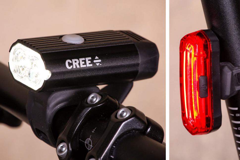
- Aldi product ref. 086287232202700 (discontinued)
- Rear 3.7V 300mAH and Front 1050mAH lithium cell,
- Specified to run for 3-5 hours (<100mA and <350mA),
- Found to run perhaps 20 hours flashing low intensity (15mA and 50mA),
- Charge 3-4 Hrs and 4-5 Hrs (<100mA and <350mA).
LED lighting similar to Bikemate units above but suitable for operating from a bicycle Dynohub (permanent magnet generator). With no battery and no power switch preferably.
By comparison, the simple regulator (AL-0035-01?) near the bottom of this page would run lighting similar to Bikemate lighting in a low-intensity mode with a vintage dynamo (GH6, GH8 or GH12). More light with modern dynamo.
English language interpretation of source blog; https://www.cyclingabout.com/dynamo-hub-power-drag-testing-schmidt-son-shutter-precision-shimano/
 Sturmey-Archer's logo dynOhub for their bicycle hub dynamo does not appear to be a registered trademark but would be copyrighted. Bicycle dynamos do not have a commutator and brushes so it does not output direct current, to be correct is not a dynamo. More correctly called a single-phase permanent magnet synchronous generator or a magneto. The symbol is a sine-wave generator signal source.
Plan for a bicycle dynamo lights and battery manager
Microcontroller-based bicycle dynamo light and battery manager with a speedometer. Design idea and exercise with STM32 microcontroller. With interface by USB cable to a tablet or any computer.
The dynohub (such as a Sturmey-Archer GH6, made 1944-1983) is rated at 6V 1.8W and will output up to 20V when the bike is ridden fast I understand. If we assume the dynamo will deliver 300mA then the output power is up to 6W. To get the maximum power from the dynamo, the current taken needs to be limited so that voltage does not drop severely.
I also understand that modern bicycle hub generators work from 2 MPH, produce up to 30V out and are rated 3W at 6V (0.5A). That is up to 15W. The firmware should include calibration of its measurements as well as optimising the generator's maximum power transfer and storing these calibration constants.
- Manage two-cell NiMH battery charging using a coulomb counting method. Other circuit variants for Lithium-Fe-PO cells were also developed.
- It is best not to remove the batteries so that the battery state of charge and capacity information is retained. Therefore use the USB port charging input preferably to take the battery out for charging.
- A lithium cell's state of charge can be determined by the voltage and charging current between low, medium, and high. NiMH batteries can only be determined by the voltage and charging current between low, medium or overcharged.

- Recalibration of the battery's state of charge and capacity if the battery is removed. The coulomb counting system with voltage sensing of a high state charge and discharge limits. An assumption is made that a replaced battery is charged and its capacity is low allowing the unit to charge a replaced discharged NiMH battery a little, quickly and the remainder of the capacity reached slowly 0.03C (50 hours). Alternatively, a replaced lithium cell can be fully charged at a fast rate.
- It is important that the Lithium cell holder or a connector should not allow the cell to be fitted with reverse polarity.
- NiMH cells fully charged is usually determined by fast charging with a high current and detecting a small voltage increase (or temperature rise), which occurs when the cell is overcharged slightly. The dynamo power is too variable to use this method but the coulomb counting method instead also monitors for overcharging. This method can be used to characterise a replaced battery if a USB power source is connected.
- Lithium battery is more efficient only requiring charging 110% more power put back rather than 150% that a NiMH requires.
- Rapid charging LiFePO4 is not possible but they charge at 0.3C, 0.5C or 1C (1-3 Hrs) depending on the type chosen. By comparison, NiMh cells can be charged at up to 0.4C (2.4Hrs) [Some Varta button cells 2C or higher} or NiCD 2C to 4C (15 or 30 minutes) depending on the type chosen.
- Lithium-ion Phosphate (LiFePo4) - is a slightly lower capacity Li-ion, with fewer raw materials used. 1.2Ah or higher. Fewer safety precautions are required.
- None of the circuits supports Lithium-ion (Li-ion) - these require additional safety circuits within the battery that disconnects the battery if the supply voltage is too high or the cell voltage drops too low.
- Lithium cell charging by constant voltage with current limits. The cell mostly takes care of itself, but lithium must include timers to stop charging if the cell does not complete a stage. The variation I propose for a bicycle is the timers are reset, paused, or extended or the final finishing stage is abandoned if the bike stops or slows. https://www.power-sonic.com/blog/how-to-charge-lithium-iron-phosphate-lifepo4-batteries/
- A 5V supercapacitor is also a good choice the charging is simply constant voltage at as high a current as the power supply can deliver. 10F would deliver 100mA and drop 3V for 300 seconds (5 minutes) with progressively diminishing light output.
- The USB port can also provide dynamo power output.
- On PCB bootloader switch for fast programming via USB port plus software debug connector.
- Software functions;
- Switches to set Dynamo output power or USB battery changing power input.
- Switch to turn the lights off/on/flashing.
- Battery charge status LED.
- USB connected status LED.

The tilt sensor is used to reduce or increase the power taken from the dynamo using parameters set by the cyclist, such as when going up or downhill plus speed.
LED lighting is much brighter than incandescent lights, such as pictured. These lights do work in the dark if placed low down to light the curb, but the lighting law changed and this is not done now I guess because the light could be mistaken for a tail light? In any case, a light should be placed higher so the cyclist can be seen. Red rear lamps are difficult to attach to the rear rack if you have pannier bags fitted.
LED dimming or intensity programming is to be handled using a pulse width modulator (PWM) running at 100Hz to 300Hz.
The first proposal for the dynamo power input
Could be based on an industrial motor control system similar to that found in factories but also used to manage power from a wind turbine. In this case without a power dump of excess power from slowing machine motors generating power. These circuits will only start operating when the dynamo's output voltage is 10V (about 6.5Vrms) with no current drawn, which is a little under the rated speed. The input boost section from the dynamo should be very efficient and ensure that the unit will continue to run at a lower bike speed once started up. These solutions are software-driven; 
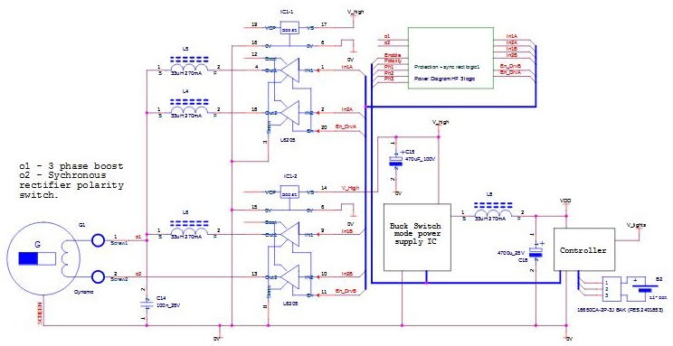
AL-0036-01F Power diagram based on motor control to operate at low-frequency boost switch mode using the inductance of the motor. Most function blocks and parts are not shown and part values are not correct. Expect the dynamo to whistle when running in the same way that the inverters and motors in some modern electric trains whistle. CAD used: OrCAD cadence.
A dynamo power management based on an industrial motor control system but scaled down looks promising but a solution based on standard IC-type power supplies will probably be cheaper.
It turns out that the dynamo's inductance is too high for this configuration to output any significant power when the voltage is boosted. That is because the period of the chopping oscillator needs to be about a second to reach full current but the period of the AC output is much shorter 10mS at a reasonable speed consequently the power output would be very low. Alternatively boost to a few thousand volts at a very low current in a millisecond would be impractical, and the losses would be too high.
The Generator model is not simple - The series inductance is so high but the open-circuit voltage is not so high, that very little power should transfer. A modern motor drive and permanent magnet motor/generator are usually wound for lower voltage, high current, and consequently lower inductance. The motor drive supply or output voltage is high, and the current regulating chopping frequency is lower, for lower losses and higher current. The high inductance of the bike dynamo does not suit working with a chopping current motor drive.
A GH6 dynamo has 5 ohms series resistance consequently at 6V, 300mA output that is 7.5V = 6V + (5R * 300mA) with no load. The peak voltage is no-load is 10.5V = 1.4 * 7.5V, at a rated 6V minimum cycling speed ??. For maximum power transfer, the maximum current drawn is <=300mA, and the load is presented by>5R.
Electromagnetic emissions and sensitivity;
Note the additional 0V screen cable bonded to the bike on both ends, the controller, and the dynamo to minimise electrical emissions. This measure is fairly essential, with the above strategy.
- There is a risk of electrical interference generation with home-fitted and wired units. Precautions such as using a paired wire should be mandated.
- But with the circuit proposals below a screened pair bond to 0V and the dynamo case both ends need not be required but recommended if a vintage AM radio be used nearby consequently better than CE mark is required.

Motor driver ICs are comparatively more expensive, have lower frequency operating and therefore require larger inductors. The benefit is the main source of electromagnetic emissions is reduced to <50% for this 2-phase design compared to the other strategies below at the same operating frequency. For a 3-phase boost, the RF emissions drop to <33%. There are other sources of radio-frequency emissions, such as the switching transitions of the power supplies that need to be addressed.
There are advantages to using a buck regulator IC rather than the software above, they are self-starting, self-protection, efficient, good regulation, and good value for money. The diagram below does not have to be a three-phase boost one inductor need not be fitted if cost-saving and lower switching losses of running one less phase are more optimal.
The diagram AL-0036-03D is a 3-phase multiphase boost pre-regulator. Multiphase regulators have lower radio frequency emissions. Changing the driver IC to DRV8955 will operate down to a lower voltage of 4.5V which works out that it will start up <50% of dynamo-rated voltage/speed. Both drivers are rated at 100KHz maximum so the inductors would need to be large.
The bridge driver proposed would be operating at maximum speed so are likely to have high losses. By comparison, the buck converter IC is optimised for high-frequency operation so is a more efficient function block compared to the previous diagram. It should not be necessary to use a screened cable bonded on both ends a paired cable should be adequate to minimise radio frequency emissions.
These multiphase converters should be more efficient than the motor driver ICs they use external transistors - but may be unnecessary cost and complication;
LTC3871-1 may do 5-30V and possibly 1.2-100V (4.5V) two or more phases boost.
LM5170 8.5V to 100V two-phase boost.
ISL78227/9 5V to 55V two-phase boost.
ADI, Renesas, STM and On-Semi make several multiphase buck controllers (NCP4200, NCP81143, PM6773, ISL6312) inverting the outputs and many other changes still do not look promising.
Comparison of motor drive or gate drive ICs;
- L6201 ST 1-4A Motor drive bridge driver - 12V minimum, Operates up to 100KHz. This driver can only hold an output high briefly so it may not be suitable.
- L6205, L6206, L6207 ST 8-52V (8-52V) 100KHz 2.8A dual bridge motor driver with various protection and current control options. These operate down to DC due to the Vboost charge pump.
- L6225, L6226, L6227 ST 8-52V (7-52V) 100KHz 1.4A dual bridge motor driver with various protection and current control options. These operate down to DC due to the Vboost charge pump.
- TLE9201SG Infineon 6A half-bridge motor driver - only operates to 20KHz, 8 - 28V.
- L99MOD51XP, L99MOD54XP ST motor drive 3x half-bridge drivers 6A, 7-28V.
- BTN8962TA Infineon Half-Bridge motor driver - 30A, 8-18V or 5.5V-40V de-rated current. The maximum frequency is unknown and is oversized.
- DRV8844 TI, 8-60V, 2.5A dual half-bridge motor driver. The maximum frequency is not specified but is probably 100KHz?
- DRV8955 TI, 4.5-48V, 2.5A, dual half-bridge, <100KHz. --- This is a reasonable solution because of the lower starting-up voltage possible but the over-voltage protection would operate often with a newer type of dynamo.
- DRV8412 TI, 11-50V, 6A, dual half-bridge, <500KHz. But for the high start-up voltage, this driver has a good operating frequency.
- DGD05463 Diodes Ltd. ISL6208, ISL6208B Renesas - Gate driver and discrete transistors. No significant frequency limit (500KHz) but requires more parts and is an expensive option.
For Vbatt (1.8V - 3.5V) to 5V bidirectional - TC78H653FTG Toshiba dual half-bridge up to 2A, 1.8V - 7.5V, 500KHz. Provides the option for a better power path with the shortest paths to and from the battery. Unfortunately, the IC can not be configured as simple half or full bridge drivers but only as a motor driver or use just two of the four drivers.
Improved dynamo input power supply;
Putting aside a motor drive IC solution, but boost pre-regulator is drafted further below in AL-0002-02 to -05. These solutions do not use a PWM mode synchronous rectifier but use a simpler boost and rectifier in software. Beneficially these circuits start at a lower bike speed and take all the available power from the dynamo.
Another variation is investigated - this circuit is efficient but does not take the maximum power available from the dynamo but does take more of the available power than would be taken wired to traditional bicycle incandescent lights. An efficient input bridge-rectifier is considered, and using transistor switches plus many discrete parts and ICs is possible. A boost stage is not included and the risk of producing electrical interference, with care, is low.

Simplified power diagram AL-0038-01E. This design features no large step-up and smaller step-down voltages. The microcontroller is powered directly by two rechargeable NiMH cells. The rectified dynamo output ripple voltage will cause the LEDs to flicker slightly which may be perceivable at low speed. CAD used CADSTAR.
This solution is similar to AL-0002-01? below, in that design Vgen capacitor is much smaller and the current taken is varied with the alternating current input so that more of the available dynamo power is taken. That is because the power factor is better.
Buck-boost configuration; https://www.ijedr.org/papers/IJEDRCP1401022.pdf
One magnetic part is saved but costs many other parts. The buck-boost configuration is an efficient solution that seems possible but difficult to implement using microcontroller timers, software and half-bridge drivers but likely to be more costly and turn out not to be so efficient. Here are some buck-boost controller IC's;
- The power used must be adjusted continually with the AC input so that;
- When the power is reduced the USB power output should be turned off,
- The battery charging rate is reduced and turned off without current being drawn from the battery,
- The LED drive is reduced and turned off when there is adequate average dynamo power,
- Enough power must be provided for the microcontroller at all times.
- Hardware over-voltage protection occurs at >55V, and may cause electrical noise? Will return surplus power to the dynamo.
- Software over-voltage >50V then turns on both boost transistors, to return surplus power to the dynamo. This software may not be required but the power factor should be overridden to prevent over-voltage from occurring.
- An efficient low side of a bridge rectifier is implemented by turning on the low side transistor alternately synchronously with the dynamo AC input. This reduces voltage drop in the bridge rectifier low-side diode. The other PWM drives the other transistor boost regulator.
- The boost voltage be set so that at minimum the troughs are above 10V, say?
- PWM for boost voltage creation is set proportionally with voltage. This carried on steps to minimise the processor's workload.
- If the current taken from the dynamo is above the optimum, its voltage will fall sharply, then reduce the current taken by setting the buck regulator power clamp DAC lower.
- Intelligent nudge up and down control - That is do not nudge the set-point if no more power is available but do nudge down to find out if more power can be taken. That is take care to prevent set-point runaway. Use indicators such as Pgood output.
- If necessary, ask a support question to find out the voltage sensitivity and voltage range of the compensation pin. Note that the simple transistor clamp circuit has a temperature coefficient.
- The power priority is the same as the non-boost above but the adjustment and switching off do not need to be done quickly because power is stored in the boost rail reservoir capacitor that tides over the AC voltage ripple.
- The dynamo current is: = I_out * V_boost / V_dynamo

Implementing a low-loss rectifier;
 Dual synchronous rectifier ICs; TEA2095T, TEA2095TE.
Diagram right SiMetrix model; AL-0034-01B - dynamo battery lights manager Synchronous rectifier controller - outputs inverted to drive MOSFET gates (small Red and Green waveforms). Unlike a diode rectifier, this circuit ensures that one of the two transistors is nearly always on.

Table of Voltage and current input from the dynohub plus estimated bike speed 10-30MPH, 5V output.
Vin Iout Power Vgen (MPH) Diode W Synchronous rectifier IC W Transistor W SR+Tr W
1.5V 300mA 0.45W 3.0V (4.5) 0.03W=0.4V*0.08A 0.11W=17mA*(5+1.5V) 0.006W=0.08A*0.07R 0.12W
5V 300mA 1.5W 6.5V (10) 0.12W=0.4V*0.3A 0.17W=17mA*(5+5V) 0.02W=0.3A*0.07R 0.19W
10V 600mA 3.0W 11.5V (18) 0.24W=0.4V*0.6A 0.26W=17mA*(5+10V) 0.04W=0.6A*0.07R 0.3W
15V 900mA 4.5W 16.5V (25) 0.36W=0.4V*0.9A 0.34W=17mA*(5+15V) 0.06W=0.9A*0.07R 0.4W
5V 0.5A 2.5W modern hub generator 0.2W=0.4V*0.5A 0.17W=17mA*(5+5V) 0.035W=0.5*0.07R 0.21W
Where the switching loss in the transistor gate drive is; 7.5mW = 5nC * 300KHz * 5V
Where the transistor switching time constant is; 10nS = 5nC * 10R / 5V about 0.3%
These are approximately some of the switching losses they are small but should be added to the table above.
Power and dynohub speed based on a Sturmey-Archer tester, assuming; 26" wheel, GH6, first 1.5V@300mA required to overcome the dynohub (5R) resistance loss. The synchronous rectifier transistor and gate drive switching losses have not been included, see AL-0042-01? further below. I have approximated the duty cycle cancels out I^2 losses or constant diode voltage drop.
No significant benefit is observed in using the IC. If the comparison is done with the boost converter, the diode is more efficient because the current-carrying part of the duty cycle is shorter, and the IC is also more efficient because the ICs Vcc would be derived from 5V and the comparison with 5V input is relevant.


Figures 11 and 3, TEA1993TS, (TEA1998TS, TEA1999TS) datasheet NXP, cut down to show just the relevant detail.

- TEA1993 plus the transistor from the table above are small from; 1.7mA * V, <8.5mW +Tr.
- TEA1999 plus the transistor from the table above are small from; 1.4mA * V, <7mW +Tr.
- TEA1998 plus the transistor from the table above are small from; 1.3mA * V, <6.5mW +Tr.
Vintage Raleigh Industries Sturmey-Archer DynoHub tester - Very Rare! | eBay
Maximum power transfer;
Software and electronics combined diagrams with a mixture of flow diagram symbols, electronic symbols and wires. The resistor-capacitor (RC) average is a simplification to show function but it is not correct a sliding average of half or one cycle should be used. Other signals that are not shown such as Pgood signal low can be used to indicate whether the main regulator is limiting. The proportional part of the loop gain due to the amplifiers as a guide should be <50, that is a 2% change in any signal should result in less than 100% change in the output voltage.
Intelligent nudge - Calibration at the maximum power output;
- At a steady speed test by increasing the current taken to see if the power increases or decreases - then adjust the maximum power accordingly.
- The test can be carried out under varying speed conditions by testing using power x frequency or voltage.
- A dummy load may need to be added. Alternatively, keep the calibration strategy simple under variable speed and loading conditions available.
- The normal operation requires that the power factor be good when maximum power is required and that not too much current is drawn from the dynamo.
Next step - build test rigs and test some of the functions

The graph right does not belong to me, so I have asked if I can use it? The green line is relevant so disregard the blue line. I have cropped the graph.
The current was presumably measured in series with the LED with a 5V drop so increases as the on-to-off duty cycle increases with the higher voltage generated by the dynamo.
User Interface and refinements;
The diagrams below are mostly worked through but for a software assessment of their viability. The low-speed crystal oscillator is not used so four port pins including 2* 0V screen pins were made available. Each PCB could be calibrated for temperature change using the on-chip temperature sensor, oscillator and microcontroller's oscillator trimming registers.
Some basic functions are provided but more controls and features such as the distance travelled log require a tablet or other computer to be connected to access those features.

Smiths BL/BMC (the 1960s-1970s) Mini speedometer,
odometer, fuel gauge with other indicator lights
Thank you for the photo https://www.digital-speedos.co.uk/
- Battery charge rate and surplus power for USB power output control,
- The tilt sensor senses the bike's inclination to determine if the bike is moving up or downhill so change the strategy between taking maximum or minimum power from the dynamo. Programmed using:
- When the battery's charge is very low the inclination control is overridden and the battery is charged at a higher rate.
- Learn mode to program the dynamo power taken strategy.
- Control switches, LEDs and speedometer proposed;
- Switch Dynamo power;
- ON 1 Minimum dynamo power and minimal charging current.
- OFF 2 Managed dynamo power for lights, managed battery charging and surplus for USB.
- ON 3 Maximum dynamo power with the surplus to USB (out).
- Switch to turn on USB charging/Learn/Set
- ON 1 USB (in) to provide charging current.
- OFF 2 USB (not in), Learn dynamo use strategy.
- ON 3 USB (not in), Use learned dynamo use strategy.
- Switch to turn the lights on.
- Lights off
- Lights on
- Lights high or flashing.
- Red/Yellow/Green - battery charge status LED.
- Red, Red/Yellow, Yellow, Yellow/Green, Green.
- Steady indicates charging or dynamo power,
- One colour flashing indicates discharging.
- All colours, Red - Yellow - Green, flashing; Fault USB and dynamo charging or battery.
- Blue - USB connected status LED.
- Steady indicates charging and connected,
- Flashing indicates connection.
- Speedometer and possibly an odometer LCD display.
- Alternatively;
- LCD display and push buttons.
- LCD Transflective, 25x50mm (128x64 dots), LED backlight 60mA 3.2V (switched off in good daylight), 64128K Display Tech systems.
- OLED 55x27mm (128x64 dots), 20mA 13V, I2C bus, W12864XA Electronic Assemblies.
- EPD 27.5x27.5mm (152x152), 2mA 3V, I2C bus, MT-DEPG0154BNS800F5 Microtips technology - no illumination.
- 2x Seven-segment LED displays plus bar graph and LEDs <100mA, 2V.

4-6. With regulators so do not require measurement and calibration for fluctuations in Vdd. These are more expensive options and (6) is the most expensive option.
1-4. A buffer transistor may be required because the open-drain output of the microcontroller is fairly high resistance and may introduce a significant temperature coefficient when driving a higher current or shunt-damped meter from a low voltage.
- Turn on the pull-up and test the port pin for a low state.
- Turn on pull-down and test for pin high state.
- If neither of those then the switch is in the open state. But if the microcontroller port pin can not be configured with pull-down on the port output low drive be used instead.
- The LEDs are driven from a high drive. The blue LEDs from an open-drain configured port.
- Some
of the meter drivers above require that the PWM be output from a high-drive open-drain port but the project files do not seem to allow this to
be done?
- Options requiring a high current open-drain port (6).
- Options requiring the output port to be set to high drive; all except for (4) and (5).
- A record of various parameters is stored once every 10 seconds. Would be a 133M location resolution for a top cyclist who can achieve 60KPH briefly.
- A log is kept with record number 2^15 stored which is the last record number plus 1 and rolls around to zero. The oldest record is overwritten by the newest record and so the next record would not be consecutive marking the start and end of the circular log. The most significant bit indicates a new journey.
- Data stored, journey number, distance, direct change and gradient travelled since the last entry. Additional information stored; supply voltage, current, battery state of charge, dynohub current and voltage.
- The 6-axis accelerometer in three plains, rotation in three plains and gravity by an external sensor, inertial sensor; 6 words (12 bytes). LSM6DSR, ST.COM (there are newer better value parts available $3ea/3000). This may be a cheaper part and a 3-axis accelerometer such as IIS2DLPC should be adequate and would be a cost-saving.
- Alternatively, in many ways, a more suitable part is; FXOS8700CQ, NXP (not recommended for new design $1.60ea/1,000) This is a 6-axis accelerometer X, Y and Z and magnetometer X, Y and Z. so can measure absolute tilt and acceleration. NXP makes many two-axis accelerometers that are less suitable and do not operate below 2V. There are many other makers and some are 9-axis.
- There is a risk that with a new design, a key part suddenly becomes unavailable for a number of months. The manufacturer may be persuaded to release sample stock so that the design can be made. That is preferable to using unknown source products, PCB assemblers are very reluctant to do that. It could be possible to change the circuit board design to accommodate two or more lC types in case it becomes necessary to use an alternative.
- Calibration data for the time and all variables be stored. Calibration systems need to be developed.
- A 2Mbit serial EEPROM has been included on the circuits AL-0002-??? that is; 256Kbytes but if we do some arithmetic to estimate what might be a useful size.
- Record number; 2 bytes, the most significant bit indicates the first of a new journey.
- Different information is recorded, at the start or continuation of a journey;
- Time since last entry; 2 bytes, over 100 hours. (360 * 100), to a resolution of 10 seconds.
- Journey number 1 byte (depending on how the battery copes with start/stop cycling),
- Other data stored; switch settings, pre-power fail or restored, if these change a different information record be stored during a journey. 1 byte.
- Average Vcc, 1 byte,
- Main buck regulator output current, 1 byte,
- Battery state of charge; 1 byte,
- Dynamo current; 1 byte.
- Dynamo voltage; 1 byte.
- The remaining bytes are not used. (11 bytes used)
- The usual information recorded, once the journey has started is as;
- Distance Dynohub pulses (up to ~2M per 20 cycles) previous entry; 1Km/ minute, 10M/second, 5 revs/second, 100 cycles second, <2000 cycles. 2 bytes.
- Gradient, direction and acceleration travelled since the last entry 2*6; 12 bytes. Would need interpreting from x,y, and z acceleration information.
- Average Vcc, 1 byte,
- Main buck regulator output current, 1 byte,
- Battery state of charge; 1 byte,
- Dynamo current; 1 byte.
- Dynamo voltage; 1 byte.
- 21 bytes per record. EEPROM 256,000 bytes. No. records; 12,190 = 256,000/21.
- 33.8 hours = 12,190 * 10 seconds / 3,600.
- A 2Mb serial EEPROM should be replaced with the largest size 4Mb. Alternatively, the amount of information stored may be reduced or compressed.


The variants of the detailed circuits to choose between
It took a long time to find the parts for what I wanted to do originally which is investigate using bridge driver ICs. Most of the ICs can not be configured as simple drivers instead of motor drivers. The solution based on power supply ICs is good and was found more quickly.

Picture right Sturmey-Archer, AG - 3-speed dyno-hub, dated July 1953; 3-speed wide variable gear hub and 6V, 2W generator. 40 spoke.

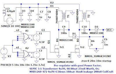
An analogue solution for power limiting is necessary to achieve maximum power transfer (see AL-0038-02?). No microcontroller is required if a manual calibration system is provided. Uses a fly-back converter but there is a trade-off with the transformer inductance selected;
- Fitting low-value inductance with high current pulses and better power factor could have high electromagnetic emissions and higher losses (4.7uH, 270KHz), works from less than 6VAC, 500mA to 20VAC, 300mA but the Power factor begins to deteriorate at 30VAC, 500mA, Or
- Higher-value larger inductance (as a conventional fly-back design) but the power transfer would not be the highest and would be more efficient (22uH, 270KHz). Alternatively, the pulse width would need to change continually to correct the power factor, achieving more modest losses and lower electromagnetic emissions. A current-mode boost controller probably would work better if this inductor value were used.
- This simulation shows that with a low-value inductor (4.7uH, 270KHz) a good power transfer efficiency at rated voltage with any bicycle dynamo. At higher bike speeds or with a higher value inductor (10uH, 270KHz) less than maximal power can be taken from the dynamo. 10uH was a calculated value that was a good starting assumption that 5V peak in and 5V output would be the worst case.


- The power factor is good with the first graph even with a higher power dynamo (4.7uH, 270KHz, up to 30VAC, 300mA or 20VAC, 500mA).
- The second graph (4.7uH, 270KHz, 30VAC, 500mA) shows when the power used is high that the inductor transitions from pulses of current to continuous current mode as the voltage * current input increases.
- In the third graph, the inductance (22uH, 270KHz) is much too high in this case but would be correct for a conventional flyback switch mode power supply in which the drive pulse width varies.
------------------------------------


The graph left lower; Would be driven by microcontroller PWM outputs in a series of steps rather than in a smooth transition shown. The simulation shows that this type of IC responds slowly and is unlikely to respond quickly enough in this bicycle case to be useful. The output voltage (red) fluctuates after the switch-on. This
simulation is not very useful.
The left top graph; is of the two transistor drains showing that they are driven alternately continually but if you were to magnify the time (X-axis) you would see the pulse width varies continually.
Control of the buck regulator compensation pin is likely to be difficult in AL-0002-??? because of its voltage feed-forward feature. Consequently, the power limiting mechanism is likely to be unstable when the current drawn is near the optimum maximum.
 This is because the regulator with feed-forward or current mode will tend to take more current as the input voltage drops before software or other control has had time to react to restore and reduce the current taken. If more current is drawn from the dynamo when the current taken is maximum then the dynamo output voltage will drop severely and could cycle on-off. This instability may be negated if the control is fast, which the additional circuit below is intended to provide. These components can be omitted so that the function is not provided.
Design files for all variants;
- AL-0039-01F Op-amp Ibatt resistor and LED PSU resistor networks.ods spreadsheets.
- AL-0040-01B Dynamo Battery Manager - Microcontroller select - Software.odt --- Updated document to follow.
- AL-0042-03B LTspice power simulation - improved transistor switching circuits with graphs generated. More functions are included in this simulation so consequently, the simulation runs more slowly. Usually, the simulation would be better to break into smaller models but the purpose of the diagram is to put the refinements together this larger simulation tests important functions operating together as well.
- List of files; There is a spreadsheet list of files.
The decoupling strategy is to place 100nF ceramic decoupling capacitors close to each IC power pin's, internal power planes 0V and Vdd for the microcontroller. I/O has 1 - 10nF COG/NPO capacitors near the connector pins. The 0V power plane provides screening for good EMC performance.
There are no thermal reliefs in the power and thermal planes. This also provides better electrical conductivity.
The part libraries are to an old standard that changed more than 25 years ago so many footprints should have the index in the centre but CADSTAR libraries have many parts with the index at pin 1. It is necessary to fix this before using the footprint or creating a footing. PCB assemblers can correct small discrepancies they have but they can not correct for this error necessarily.
--- AL-0002-01 Basic bicycle dynamo battery and lights manager - Draft ---

- AL-0002-01M Circuit and PCB's - draft. The design should fit under 100 x 100mm.
- AL-0033-01F.ioc Micro-controller selector and configuration project file draft. ---
- STM32L072C - 48 pin one test point and one spare pin.
- The input capacitor should be small (1uF) for good power factor therefore efficient power transfer but options to fit higher value capacitors in case electromagnetic emissions turn out to be high or it turns out that the buck regulator becomes unstable. If a higher value capacitor is used then the power factor will be poorer and less power can be taken from the dynamo which is the trade-off.
- A large capacitor is fitted to VCC, the main power to ensure that the microcontroller's power is not interrupted almost regardless of the battery's state of charge or whether a battery is fitted.
- After providing power for the microcontroller software is required to manage the modulation of the LED current next priority, then USB output current if there is the power to spare. The LED flicker may not be very noticeable but care needs to be taken to ensure that the brightness modulation frequency does not beat with 2x dynamo output frequency. That is led brightness modulation frequency be set to a multiple of two times dynamo frequency or be a much higher frequency.
- The battery will provide lighting power when the dynamo speed is low thereby allowing the lights to dim a little but preventing the lights from flickering severely at frequencies that are a health issue. Perhaps dimming the lights but not allowing the lights to be off for more than say 10 mS?
- This is an efficient solution with basic functions.
- There is no input boost supply rail so the circuit will not operate at as low bike speeds as other versions below do.
- The switch-mode power supply IC includes feed-forward compensation could cause a problem to occur with more current attempted to be drawn when the dynamo's output voltage is lowest and the least current is available.
- The main regulator's power is controlled by DAC and a transistor AND-ing the soft-start function. This circuit is very simple and low cost consequently has a large temperature coefficient that must be continually corrected for in software. Alternatively, the main regulator's output voltage is set using a PWM output be used.
- Speed-o-meter output - will drive a 0-50uA moving coil meter. Scale illumination output needs to be developed.
- This is driven from an open drain PWM port pin will be compromised a little by the temperature and VDD coefficients of the port pins on-resistance (~50 ohms).
- Replace the diode bridge rectifier with a bridge rectifier controller and transistors will save power at low input voltage. This will save 15% losses at 6VAC input.
- At the start of power input, the batteries are charged at a moderate rate until Vdd reaches a high enough voltage for the microcontroller to start up and take control. In this case where at startup the battery is found to be low voltage and charging then an assumption be made that the battery was fully discharged, and the coulomb count is zeroed.
- Although batteries can be changed there is little protection against the batteries being fitted reverse polarity and in this case, the current sense resistor would burn out.
- Changed the main regular to lm76002-q1 TI, this is a more expensive IC,
- Start-up down to >3.5V rather than > 4.3V with better external bias supply or-ing for lower start-up voltage.
- Also, the compensation pin can be over-driven to reduce the power output similar to driving the soft-start pin in version -01? The IC is internally compensated.
- LTC3649 ADI, 4A, 60V
- Start-up down to >3.1V rather than > 4.3V with better external bias supply or-ing for lower start-up voltage.
- Also, the compensation pin and current programming pins are available.
--- AL-0002-02? Software-driven with PFC input or software-driven with PFC boost supply for lower voltage operation --- Draft ---
PCB size under 120x100mm 4 layer components on one side.
- AL-0002-02N Circuit and PCB
- AL-0033-02F CubeMX software project file.
- Vgen is boosted by PWM so that power is stored in the capacitor long enough to ensure that the LEDs do not flicker at 2x dynamo frequency.
- The circuit can also be operated without the boost pre-regulator and includes a power factor limiting circuit to save processing power and software work. The electrolytic reservoir capacitor also needs to be removed. But if the boost regulator is used, the limiting circuit should be disabled by shorting the soft-start pin driving transistor E to B.
- STM32L052C6Tx 48 pin, microcontroller. With one test point and one spare pin.
- The meter driver is for the highest current type with a 240' movement. The movement is 500uA so the power taken is ~8mW = 2.5mA * 3.3V.
- This design and layout are to be refined after software review.
- Power Factor Correction is approximated by the software-driven varying Pulse Width Modulator boost supply. But the drawback is that boosting to a high voltage and then dropping to a low voltage is less efficient. Conversely, if the reservoir capacitor is large then the boost voltage can be lower than the boost followed by buck regulators can be efficient topologies at low bicycle speed.
- Current regulators for LED drives instead of voltage regulators to improve efficiency have not been implemented. This could be implemented in the lamp units from the 2-3V light output, with the addition of PWM outputs.
- An earlier version of this design (AL-0002-02D) used the ucc29910A PFC IC, which only requires a 5V power supply, but this design looked unnecessarily expensive and was abandoned.
- This version is suited for evaluating both with or without a boost pre-regulator strategies, whereas version -03 is more efficient. This version -02 but without boost pre-regulator is more efficient than version -01.
- The unit should have some power for lighting for up to the storage life specified by the battery perhaps, one year. Dynamo power is available immediately regardless of the condition of the battery.
- The battery could be changed the unit is protected against the batteries being fitted with reverse polarity. In addition, the unit will still run lights first priority.
- To be refined after software review.
- Add buck-boost SMP LED current drivers.
- Change the microcontroller to a larger; STM32L072R - 64 pins and has two DACs.
- Add input filter capacitors followed by series inductors.
- Implement the modifications provided to remove the input boost pre-regulator and thereby the circuit to become an improved version of -01? (above).
- The circuit may not operate to as low voltage but the risk of EMC non-compliance can be reduced if the large reservoir capacitor is fitted. In that case, there would be no PFC and the power taken from the dynamo would be reduced.
- Keep the input rectifier and over-voltage protection formed of low-side software-driven transistors which have lower losses than diodes used in version -01?. Therefore short boost inductors.
- AL-0002-03o circuit and PCB. - This variant is similar to version -02?.
- STM32L052C - 48 pin. There is one spare pin and one test pin.
- This variant has a more efficient battery charge/discharge power switch because an n-channel MOSFET is used that is driven from the higher boost 3-5V supply. But the battery current drain is higher although not too significantly when switched off because more functions remain connected.
- This variant will operate if the battery cells become shorted (I do not know if this is a serious issue with NiMH cells compared to the older NiCd type). Software is required to turn off outputs when Vcc voltage is low to keep the microcontroller powered from the reservoir capacitor.
- If it is found that a battery cell is shorted a low-intensity warning such as slow rate flashing of the battery state of charge LEDs when dynamo or USB power is available.
- A circuit is included that limits the battery charge current;
- Vcc maximum is controlled by the battery current monitoring amplifier but this function has not been fully developed. A diode is shown "do not fit", to disable this function.
- The amplifier's gain would need to be calculated and resistors selected for the chosen battery. There is no software adjustment of this current limit.
- The additional circuit could cause instability in VCC, poor current monitoring and unnecessary complications. Conversely, the circuit is more responsive and likely to have better than software-controlled current limiting.
- The Ibatt amplifier does not include switch gain and current range for charge rating measuring but is suitable for measuring current and coulomb counting.
- Power-consuming peripherals and the microcontroller modes are set to low power or turned off when there is no dynamo or USB power.
- This circuit can operate like version -01? without the boost pre-regulator, but power management must be well developed. That is because the microcontroller is powered by the Vdd capacitor in which software must manage the loads to retain enough power for the microcontroller during the zero voltage part of the AC input from the dynamo.
- In this case, the power limiting circuit in version -02? could be pasted into this circuit (scroll up this blog to see).
- This design may offer a small improvement on version -02? in handling a higher battery charging current.
- The battery switch transistor when turned off still provides a little power for the microcontroller.
- Unfortunately, there is a small but significant current drain from the battery to the buck regulator consequently the battery may be run down over winter where a bicycle is only used in the summer. Whereas other variants the NiMh battery should have some power for up to a year so the lights can always be used and the battery would have a little more life.
- The meter driver is simple but the most expensive variant or the most efficient. The movement is 100uA but would work with a 30 or 50uA movement with better damping and lower voltage VDD.
- The battery could be changed the unit is protected against the batteries being fitted with reverse polarity. In addition, the unit will still run lights first priority.
-- AL-0002-04 This variant uses Lithium rechargeable (LiFePo4). Uses the micro-controller op-amp which is good enough but must be turned off when the unit is inactive to save power. -- Draft ---
- AL-0002-04J PCB and circuit.
- AL-0033-04C MXcube microcontroller project. -- To be updated
- Uses STM32L052C 48 pin. - One test pin and one spare pin.


- Lithium protection is less demanding than for a laptop because the cell is a safer LiFePo4 type.
- In this case, the uC be permanently connected to the battery and software manages the battery protection.
- The power path is more efficient because the voltage is higher and the currents are lower so I2R losses are smaller.
- VCC power supply is disabled to save power when there is no USB power in or dynamo AC input.
- Speed-o-meter output - to drive a 0-30uA moving coil meter. There is also a scale illumination output but this needs to be developed.
- This is driven from an open drain PWM port pin will be compromised a little by the port pins' on-resistance temperature coefficient.
- The second lights regulator provides up to 400mA at 1.2V to 5V and is described scroll down below.
- Although the battery could be changed and the unit used to charge batteries there is little protection against the batteries being fitted reverse polarity and in this case, the current sense resistor would burn out.
- The lithium cell holder or connector must include protection against reverse polarity connection.
-- AL-0002-05 This variant uses Lithium rechargeable (LiFePo4). Uses the on-micro-controller op-amp and another more accurate op-amp which is good enough but must be turned off when the unit is inactive to save power. -- Draft ---
- AL-0002-05G circuit and PCB
- AL-0033-05D.....ioc STM32L151RCTx 64pin microcontroller project file - has unresolved clock issues.


- This variant is similar to -04?
- Uses STM32L151R - 64-pin microcontroller.
- This version uses a microcontroller with op-amps;
- There could be a cost-saving.
- Small signals are tracked across the PCB rather than amplified at the source then large tracked across the PCB. This may not be an issue.
- The op-amps are not optimal and the input current is quite high.
- A speed-o-meter moving coil meter output is provided. The LED illumination drive needs to be developed.
- Although the battery could be changed and the unit used to charge batteries there is little protection against the batteries being fitted reverse polarity and in this case, the current sense resistor would burn out.
- The lithium cell holder or connector must include protection against reverse polarity connection.
- Circuit and PCB AL-0038-02D
- The output capacitor is of a modest value consequently Vcc will have a high ripple voltage.
- A boost voltage mode type switch mode power supply controller that has no feed-forward and is not current mode control would be the most manageable for optimum power transfer.
- Buck controllers but using the high side driver to form a boost regulator, NCP1589A, NCP3020, NCP5269B, A6727, L6726A - that manufacturers On-semi and ST confirm.
- The synchronous rectifier at the output to save power would make this an efficient solution. Because this option is not implemented on the high side this is a flyback converter instead of a more efficient SEPIC converter, a capacitor is shown to not fit, therefore requiring a snubber network that will waste some power.
- It is possible that the synchronous rectifier won't work efficiently due to the cross-conduction prevention mechanism not configured for this application, so there is an option to use a diode rectifier instead.
- An integrated circuit high side synchronous rectifier circuit could be added to replace the diode option. Using a transistor and a high-side synchronous rectifier controller based on ICs such as; TEA1993TS, TEA1999TS, UCC24612 or SRK1001.
- The dynamo current is calculated from the regulator output current to limit the average dynamo current. Consequently, the dynamo power taken is limited in a simpler and more efficient way.

- The design is incomplete, and component values and footprints are wrong. The PCB shows an early design step of grouping functions together placing those groups and some routing to help to improve the placement. Some footprints need to be defined to replace the temporary single inline connectors placeholders.
- The optimum current limit is set using a voltage clamp on the boost regulator compensation pin programmed with a potentiometer. The output current is set as a proportion of input voltage, up to about 3A.
- A switch allows the speedometer meter to be used to calibrate maximum power transfer.
- Switch the switch to calibrate maximum power transfer. The dummy load is also connected;
- Keep the wheel spinning steady speed that puts the meter needle about mid-scale.
- Adjust the potentiometer for maximum meter deflection which is maximum power. It will be necessary to let the wheel speed reduce in order to keep the meter reading about mid-scale. The potentiometer should then be reduced slightly.
- You will observe that the power will increase or reduce with wheel speed. The power will drop severely at very low speeds. This poorer low-speed performance may be improved by reducing the potentiometer a little if required.

- Many of the analogue functions are likely to be unstable and some circuit modifications may be necessary if this is a problem.
- Define missing PCB footprints, which have SIL connectors as placeholders.
- Complete PCB layout, including adding more decoupling capacitors.
- The circuit does not slightly increase the current taken with dynamo voltage increase. This would have contributed a little extra power output.
- The circuit does not ensure the load is >5 ohms. Consequently, not all available power will be gathered at low dynamo speed.
- Mounting connectors could be added for a microcontroller evaluation board such as; https://www.st.com/en/evaluation-tools/32l0538discovery.html with 0R jumpers to swap electronic functions with microcontroller functions.
- Battery and charging circuit are not included but a Lithium cell and L6924U, L6924D and probably other IC battery charging controller IC will work with AC ripple on the power input. Other IC battery charge controllers such as bq25017 have more features.
ToDo - list all variants of AL-0002-??? and AL-0038-02?;
- The microcontroller needs to be changed to a 64-pin device. To provide function or design revision flexibility.
- Add backlight power for the speedometer.
- Consider using smaller batteries. Therefore change the battery holders.
- Consider removing the variable voltage control of the 5V USB output. Software be configured to use the battery to fill in fluctuations in supply to the 5V USB output but leave reserve for the lights.
- Consider replacing the battery with a super-capacitor, (This is simpler to manage)
- It is unlikely that the microcontroller needs to be kept running because there is an EEPROM for logging data. But a small two-cell NiMH button battery, to maintain microcontroller Vdd and run the lights initially could also be added possibly?
- If the time and date clock were required then the microcontroller's 32KHz crystal oscillator should be added and a NiMH two-cell battery should be connected to the uC battery pin.
- Main power supply compensation needs to be calculated. It is roughly based on the datasheet examples.
- The input filter stage needs to be added, for the dynamo power input. A screened cable would also resolve the issue, this is catered for but could not be relied on to be connected properly.
- Select suitable boost inductors to replace the placeholder parts used. Depending on the selected operating frequençy for example 68uH at 100KHz.
- Consider replacing rectifier diodes with synchronous rectifier IC circuits such as TEA1998 or TEA1999.


- Consider adding a buck-boost LED current source for all lights or at least for the front light for all AL-0002-xxx variants. As AL-0002-04? or AL-0002-05?. Alternatively add a PWM output for the power supply to be located in the light unit to form a 2-5V input light unit, instead of the PWM-driven power output.
- Change the accelerometer to a cheaper or likely better availability 3-axis part.
No load loss due to the crowbar-shunt regulator is less than; <1W= 0.3Ag*1.5Rg + 0.3Ag*1.6Vt
This simple regulator would run Bikemate lighting pictured near the top of this page in low-intensity mode.
The cost and benefit of using a more expensive microcontroller with more functions on-chip Some people cost things on 5p per pin used whereas other high volume users tend to simply avoid integrated circuits where cheap discrete parts can be used. It is not clear-cut without asking a PCB maker and assembler to price some variants in the volumes you are likely to use.
STM32L072R or STM32L052R are probably good choices along with using an external dual operational amplifier. For the Ibatt monitoring, it will be necessary to periodically turn off all major current inputs to calibrate the battery current measurement. The A-to-D converter reference is VCC with a 1.25V internal reference connected to one channel to measure VDD. This works over the entire voltage range of a two-cell NiMH battery.
STM32L0??? And STM32L0??? Do not have op-amps and better-suited external op-amps are used.
STM32L151, by comparison, is more expensive and has two op-amps but the cost of the extra parts saved may break even.
The op-amp PGA feature is only a simple 0V-referenced set of fixed gain settings for the op-amps.
STM32L433 some variants with 64 or more pins have a buffered reference output, so the A to D converter can be referenced to that instead of VDD, which varies. In addition, there is an op-amp.
STM32L475 (two op-amps) variant with an on-chip reference buffer. This microcontroller comes low down in the selection tool, so may be a poorer value for money than the newer microcontroller below.
STM32L552 have two op-amps, and a buffered reference output but in both cases, if the buffered reference is used it is only accurate with high VDD otherwise it reverts to tracking VDD. This is one of the faster newer low-power microcontrollers that may be more suited to the variable PWM controller of the boost regulator.
STM32F303 (four op-amps) or STM32F072 (no op-amps) are lower cost, without the low power and lower voltage features. Is low enough power to be used with any variant with the boost regulator or lithium cell to provide VDD.
--- STM32L072R is probably the best choice in all variants. ---
Another possibility is to have several variants developed and made. Then have one or two of each variant on a panel of PCBs and put as many different PCBs on a panel as possible. But this may not be worthwhile PCB makers now put as many different jobs together on one panel in any case so it is necessary to check?
Have at least two PCBs made but not assembled but the cost difference of assembling just one or all may now be comparatively small. That depends on whether pick-and-place or manual assembly is chosen. It is necessary to ask each PCB supplier/assembler the same combination of questions?
PCBs that are not assembled can be stored for up to 18 months and be assembled successfully. After this period of time, the metal pads may have oxidised too much for the contact to be reliably made.
 A hub generator would be improved if it were a two-phase (4-wire) or three-phase (3-wire) because the current is output continually. Ripple would be 40% for a two-phase generator and just 15% for a 3-phase generator when full-wave rectifier.
Evaluation of a home-made bottle generator;
See appendix in the blog; https://blog.andrew-lohmann.me.uk/2019/07/bicycle-hub-dynamo-maintenance-project.html
Picture right; Astrosyn motor bottom left.
- L7987L st.com; 4.2W = 55V x 1.7 x 2 x 23mA,
- LMR36510 ti.com; 4.6W = 60V x 1.7 x 2 x 23mA
- LMR36506 ti.com; 3W at 5V out.

------------------------------------------------------------
LED power supply for one or many identical LEDs connected in parallel. An LED running at 100mA is very bright and the maximum current available probably could be reduced. White LED's voltage drop is 2.8V - 3.2V or <3.5V - 4.2V depending on the type but Red LED's voltage drop is about 1.7V.
Average current limited set by pulse width modulator for diving any LED. The LEDs used if connected in parallel in the same assembly and from the same manufacturer batch. Alternatively, lower voltage drop red LEDs can be paired in series then multiple pairs connected in parallel.


- Using an STBB3JCC buck-boost switch-mode current regulator
- This regulator's current output could be re-configured by changing the programming resistor (Resistor = 100mV / Current_required).
- 100mV Feedback +-10mV.
- The current is set by a resistor to 400mA.
- The current is reduced by Pulse-width-modulation
- 100-300Hz, with <300uS turn-on time when the current output ramps and the output capacitors determine the ramp-down rate. Determine the average current and any LED colour change.
- If the input power has an AC ripple component from the dynamo the frequency may beat with the PWM frequency causing the LEDs to flicker. Therefore in this case use the highest PWM frequency 300Hz. [This warning is applicable to AL-0002-01? and other variants with no pre-regulator]
- The LED lamp is connected between Lamp- and Lamp+


- Alternatively, a regulated 5.2V can be taken from Lamp+ and 0V.
Data-sheet right; A single red LED will drop 1.7V consequently the LED current will reduce below 2.7V but not so severely as if a simple series resistor were fitted. In any case, a simple resistor would be fine a 7:1 current change would be noticed but would not be severe but a 2:1 current change would not be noticed. BCR421U's current should be programmed by fitting a suitable external resistor between 10mA and 100mA but can be set to a higher current.
LED lights; - see section of Bicycle-hub-dynamo-maintenance-project
---------------------------------------------------------------------------------------------------
Conclusion
I have used this project as a design exercise to learn and formularise myself with some of the STM32 series microcontrollers and keep myself up to speed using CADSTAR 18 and other CAD tools. I have not been paid for support just now on that circuit and PCB CAD tool because I am not working. For example, there is a feature to click on a net and move promptly to other locations where it is used that I would like to use.
I have not explored whether I have chosen the best combinations of the microcontroller's peripherals for the functions required, particularly timers. This is partly why the design options are marked draft, they require software review write draft software for some function blocks.
I have also considered software solutions by drawing a solution in electronics, which software engineers tend to call hardware. A hardware model in springs, levers and wheels is good but the software solution could be very different. A springy Reynolds steel sports bike frame can be applied in inductors capacitors and resistors but electronics work better with the stiffness of bonding 0V everywhere for screening but uses springiness as well, both giving immunity to road vibration or electrical interference and efficiency of power transmission. Transmission line theory applies to electronics. Maths such as averaging a signal over one cycle of the dynamo output are easy in software.
Technical discussion on the electronics community.st.com/s
Related blog Bicycle-hub-dynamo-maintenance-project
Power for a low-power wireless long-range device.
For smaller Internet of Things a D-Cell lithium primary cell may last up to a decade, alternatively, an energy harvesting strategy can be used. Depending on the power required.

A much smaller sized variation of the above design could be developed. http://www.rotalink.com/ http://www.rotalink.com/our-products/10/ac-motors-optional-gearboxes.html make geared motors with strong ball-bearing bearings. For example;
- 4116 synchronous motor (48V or 24V) + 227 gearbox (25:2) with ball bearings.
- SB2513 bipolar 24V stepper motor + 222 gearbox (~7:1) with ball bearings.
The bearing is strong enough to stand having a pendulum and weight fitted to create up to say 1W.
A lower power, power supply based on a higher voltage say 24V 48V motor based on the circuit AL0002-01? above may be suitable using a low power switch mode power supply. Power factor correction would be an unnecessary complication in this case but is not required with a multi-phase generator anyway.
- 60V input, 50mA output switch mode power supply such as ADP2360 may be suitable?
- L7983, 300mA output switch mode power supply 4-60Vin, 2.3 µA shutdown current.
- LMR36506 ti.com; 600mA output switch mode power supply 3-65Vin, 2.3 µA shutdown current.