This blog also explains simply how cars, with or without a regulator, magneto or coil ignition, or starter motor, worked. Poisonous environmental and human factors.
The mechanical cut-out or cut-out and regulator can be replaced by an electronic rectifier and an electronic regulator. This blog develops electronics that will also deliver more of the potential power circulating in the dynamo, not traditionally available at lower and higher RPM. Using a buck-boost switch-mode regulator and software similar to that used by solar power inverters, which uses a trial-and-error system to deliver the maximum available power, usually called Maximum Power Point Tracking.
These circuits provide extra power to reduce the car battery's workload and improve its lifespan. They will not provide all the power required across the RPM range, but will deliver more power at lower speeds than originally and will increase power or place a lighter load on the dynamo at high RPM. To improve the optimisation, a calibration curve needs to be created, starting with the maximum current measured when the field windings are driven at full voltage. The calibration curve should then be tuned on the fly to maximise power transfer, thereby maximising power extracted from the dynamo.
This blog also discusses the history of electrical systems, cars, and lighting, as well as ways to economise on the power required using LED lighting so that the original car dynamo can be kept. In addition, the battery can be better cared for. I have not made and tested the electronics on this blog. So, take care with these design suggestions, and don't expect as much power or a wider speed range as with a generator with more poles, such as an alternator.
Pitman's motorist library, Morris 8 and The Morris Minor to 1956,
Dynamo, earlier cut-out and later cut-out and regulator control box, not as labelled.
The regulator and cut-out remained fairly unchanged between 1934 and 1970; the design was quite good for its time. After about 1970, the alternator significantly improved automotive electrical systems by delivering full power across the engine's RPM range. Cars standardised on a 12V negative chassis to better suit the silicon-based electronics used. LED lighting can greatly reduce power consumption. Still, other added electrical systems have increased the power system's demand. The buck-boost regulator in this blog would operate in buck mode to increase the dynamo's output power at higher RPMs. A simpler boost regulator could do a small part of the job at low RPM, which I have included. An electronic regulator that operates on the field winding but, instead, improves power transfer rather than regulating the voltage that the original regulator would if fitted.
Cars were once toys that only the rich could have, but they became useful tools, enabling transportation and allowing people to travel for leisure and work. Cars remain toys, with their noise, risk, and fun, and the challenge of managing the inefficiency and mismatch between the engine and the road by changing gears is their most attractive feature. The noisy, supercharged 1920s Bentley is preferred over the fast, non-supercharged classic that W. O. Bentley preferred. They are heavy cars that the owner needs to manhandle rather than drive. All this time, the bicycle was the better option; public transport and walking were common alternatives. My 1946 Lenton Sports bicycle was made during a time when bicycles were at their finest. This blog discusses early car electrical systems and ways to optimise a veteran or vintage car you wish to continue running with the original dynamo. I have also included additional historical technical details about cars and bicycles.
By 1890, bicycles and electric vehicles were quite good, and the horses, which suffered dreadfully at the hands of humans, as told in the story Black Beauty, first published in 1877, started to be retired from human exploitation.
‐---------------- The issues with the dynamo electrical system ------------
The battery was not charged at an optimal rate. Still, it was a compromise, which meant the battery would swing between trickle charging, overcharging, and powering many of the car's electrical systems while the engine was idling. This was improved upon with the electromechanical regulator but resolved with the introduction of the alternator, which powers all the car's electrical systems, even when the engine is idling. For earlier cars, another blog is more relevant: Bicycle Dynamo: maximum power and battery charging manager
Automotive LED lighting can reduce power consumption and increase light intensity, but the field-current-setting resistors need to be changed; a better plan is to fit a regulator. This blog proposes the buck-boost regulator and recommends LED lighting, but not recalibrating the original charging system by changing the field-winding series resistors in the earlier simpler controller or the dynamo.
---------------------- BUCK-BOOST SWITCH MODE POWER SUPPLY ------------------------
The boost switch-mode circuit will provide a little more power at a lower 600 RPM. Buck mode is beneficial at higher RPM: the regulator can reduce current and therefore the dynamo's heating, provide higher current output, may extend the life of the dynamo's brushes, or deliver more power at high RPM.
The remnant magnetism in the dynamo is required for it to start generating, but alternatively, the battery can be used instead. But in the conventional system, the dynamo also has to produce more than 5 times the power that the field requires to start generating. That is, the field is supplied with only ~20% of the dynamo's power. In contrast, this circuit can deliver nearly 100% of the dynamo's power to the field at lower RPM and thereby continue to operate at lower RPM.
Conventionally, the dynamo needs to generate more than nothing, but some dynamos need a bit of revving to start if they haven't been used for some time. But setting to high charge and waiting longer should also work, unless it has an electronic regulator that requires a 1V or more likely 2V threshold to be crossed before it starts. I have also included some transistorised regulator control box circuits based on those likely to have been used in the 1970s; they have fewer electromagnetic interference (EMI) protection and prevention measures than modern automotive electronics have.
The second and subsequent circuits use all the power generated by the remnant magnetism in the dynamo initially to power the field, so it builds up to full generating power quickly and provides extra power sooner. The dynamo must produce at least 400mV to start up, or, in the example with the relay, instead of an auxiliary boost regulator, a little more voltage than nothing is required, the same as the electromechanical regulator and similar to how no regulator would behave. A web search tells me the remnant voltage is 2V for a 12V dynamo, therefore 1V for a 6V dynamo, at a modest RPM.
At higher RPM, the buck switch-mode circuit can deliver a lot more of the power normally recycled back to the dynamo for the car's electrics. I suggest current limits that increase in power for, say, 15 minutes, then reduce to 120%, 150%, 200%, or the maximum available. The buck-boost circuit is likely to be more useful with pre-World War II cars. The maximum may be 25A, which is 30A dynamo current less the field winding current.
The example I've used is the later Austin 7 D45D dynamo, which is rated at 1,200 RPM, at which the circuits will produce the same power as the original system. But the buck-boost circuit produces more power than the original car's control box at both lower and higher RPMs. The circuits are designed for 6V electrical systems but have a switch for 12V electrics. The electrical system will have better voltage regulation.
Some cars with magneto ignition can be hand-cranked to start with a flat battery. A flat battery can be high impedance and, therefore, will not charge. The simpler charging systems of earlier cars, which did not have a regulator, would therefore supply the battery with a progressively rising voltage that would charge the battery and then overvoltage if the battery had not recovered, pop bulbs and blow fuses (including the field fuse) because the battery cannot regulate the voltage anymore.
Expectation:
Graph showing the expected benefits for each of the circuits
AL-0060-??? is not to scale, and curves may be the wrong
shape and is just the lower half of the RPM range.
Boost Mode:
The region to the left of the dashed line is the boosted power lower RPM operating.
The solid region is the lowest operating RPM extra power area region.
The region filled with horizontal lines is the boosted power.
Buck mode:
Extends to the right beyond this graph, where the dynamo produces the same maximum current, but at a progressively greater voltage, which is converted to a higher current at the correct lower voltage, or the A dynamo can be run at a lower power level.
The exponential output curve does not continue above 6V field voltage, but becomes almost flat at 13A dynamo output in this case, due to the core iron saturating at a maximum amount of magnetism.
At 600 RPM, somewhere between these two models:
Maximum power transfer. If the dynamo model were a voltage and a resistor, it would deliver a maximum power transfer of 6.5A at 3.5V, boosted to 3.2A at 7V, with 2A for the field winding and 2A for the coil supplied by the dynamo and the battery. This thereby reduces the battery drain to 1A.
But if the model is a current source with a variable voltage limit. In this case, the voltage will still have dropped to 3.5V but at a current of 13A. This can be boosted to 7V at 6.5A. That is 2A for the field, 2A for the ignition, and 2A or so for trickle charging or some auxiliary circuits, such as some of the lighting.
By comparison, without the boost regulator, the output would be 7V at zero current, so there is no current for the field, so the dynamo could never generate 7V or sustain any lower voltage and consequent lower field current. That is, the dynamo could not start up at this low RPM.
The likely outcome is that the dynamo will generate a combination of models (1) or (2), and the power output will spiral down to nearly nothing at lower RPM. Either way, there will be more power, but not enough to run all of the car's electrical systems at low RPM.
At 1,200 RPM, the dynamo would deliver a maximum of 13A at 7V or 8V, with 2A used by the field, leaving 11A. That is the same as the dynamo's specification as the original system. In which the charge rate would be lower than desirable when the battery needs charging, and all electrical ancillaries are in use. At 2,400 RPM, the dynamo would deliver a maximum of 13A at 12V (over 14V). The buck regulator could deliver over 26A = 13A * 14V / 7V, less 2A for the field winding, leaving 24A. In this case, the average field current could instead be reduced, so that less power circulates in the dynamo whilst delivering the same power as the original electrical system.
At 3,600 RPM, the dynamo could deliver a maximum of 37A, 7V from 21V, and 13A. The circuits include an overvoltage clamp protection, which produces shorting pulses to return the dynamo's current as motive force, reducing the torque taken from the engine.
The graph shows a small section of the dynamo power output. The upward diagonal lines' shading region is the original power output, and the downward diagonal line region is the buck-beneficial region. The areas to the left are the boost-mode region. The solid region is the boost - extra power region. The graph extends further to the right and has the potential to generate significantly more power. The electrical system should withstand a higher current than originally would have, but only for a short time, while the battery demands more current.
These circuits do not suit a magneto-only car, such as the first car below, but are suited for a dynamo in the second car below, which also has a magneto. But the bicycle dynamo project, Bicycle Dynamo, maximum power, and battery charging manager may suit the first car below if the magneto has power output for lighting?
The first car is an 1897 Vallée Vis-à-Vis, which is the earliest example I've discovered of a car with magneto ignition, so the operator did not need to carry a dry or charged-up battery with him, except for battery-mode ignition for starting, which this car might have had. Lucas Industries started making magnetos in 1896.
The second video above shows a Swallow car (later renamed Jaguar Cars) body mounted on an Austin 7 rolling chassis. Holden Australia produced a body for the same Austin 7 rolling chassis. Dixi USA made Austin 7s from kits; BMW purchased Dixi, and the Austin 7 kit was BMW's first car, which they converted to metric parts. Datsun also made a copy of the car, which they licensed later.
Both cars' engines can kick back and severely injure the operator or cause other damage if the timing is not set to retarded before starting. From about 1930, cars incorporated centrifugal and vacuum timing advance, so kickback is less likely to occur. Placing your thumb on the handle, facing the same way as your fingers, is an important way to reduce the risk of injury if kickback occurs. The technique required was to turn the engine over until the compression cycle was felt and then swing the handle quickly over compression. A few veteran cars in museums that are kept running injure someone every 5 or 10 years, starting them.
At this time, many car makers made rolling chassis, and carriage makers made the car bodies. For example, at first, Rolls-Royce just made the rolling chassis; late in the car's life, the saloon car body was often replaced with, say, a fire engine body and equipment. But whether it was Britain's best car at times, Rover at least shared that claim. Early Rolls-Royce car manufacture allowed two weeks for making and setting the rear differential gear; after that, the gears continued to get smoother over the life of the car. Car and bicycle gears, of course, continue to get smoother during their lifetime or wear out, depending on the maker.
Rover made some of the first modern-type safety bicycles and used the very efficient Lloyd's roller shaft drive on some of their later bicycles. There are conflicting claims for the invention of the first safety bicycle; it could have been made in the UK or France. Similarly, with lighting, many people were involved in the development of incandescent lighting. The horn, bell and lighting were important for bicycles and motor vehicles, and many people were involved in improving the lighting since the 18th century; see Incandescent light bulb - Wikipedia. Swann's carbon filament light bulb was succeeded by the tungsten filament lamp. A major development was the chain drive, but there were lots of significant developments around the end of the 19th century. Then lots of improvements in steel making and tempering, particularly after each of the two world wars.
Austin 7s had a pull-cable mechanical starter, a dynamo, battery, and lights. In 1923, an optional starter motor which became standard in 1924, plus tools including a crank handle. But the earlier 1920s Austin 7s used magneto ignition, and the car starts well enough on a magneto. But generally, magneto ignition has poor ignition power at low RPM; therefore, cars using it solely could suffer from poor starting. On the other hand, you can start a small-engine car with a flat battery on the starting handle. Later, Austin 7s used the battery and dynamo with the resistor, contacts, and capacitor Kettering ignition system. This blog mostly covers Austin, but I mention Morris and Riley, for which I have some vintage books for 1930 to 1940 models of these cars and also the Villiers motorbike engines. Villiers used a metal or a selenium rectifier (which might be one of the earliest production uses of a semiconductor rectifier when a cat's whisker crystal had been replaced by the point contact diode for the radio detector). I also found information on early Ford cars on the web.
Cars like these, made between 1920 and 1970-73, are what this electronic unit can improve the electrical system of. There is no commercial version I know of, making a unit that has similar benefits to these circuits. But any of them will be expensive to develop, and using evaluation boards is limited because they tend to be low-powered.
The first practical electric motors and generators were developed between 1832 and the 1880s. Two principles were demonstrated by Benjamin Franklin's electrostatic motor in 1748 and Michael Faraday's electromagnetic motor in 1821. Practical electrostatic motors are being developed and used now; they are low-speed, high-torque, higher efficiency, and lower material cost but are lower density than a conventional electromagnetic motor.
Raleigh bicycles, the Austin 7, and Mini cars are all classless icons of British manufacturing in their time. The Austin cars were technically ahead of many other makers' cheaper, popular cars. Classless up to a point, people were pushed towards cars rather than bicycles, walking and public transport, which they may be unwilling or unable to afford, to drive them, and those systems they could handle became less available and more difficult to use.
The electrical systems that these electronic unit options can improve.
The mechanical regulator
Is a relay; its contactopens and switches the field winding off when the voltage gets too high. The snubber resistor across the contactreduces the back-EMF (voltage) across the regulator contact, thereby minimising spark erosion of that contact. The field magnetism and, therefore, the dynamo output decrease slowly, even more slowly with a semiconductor regulator that has a diode for snubbing, and the dynamo's field iron will remain magnetised to some extent.
Therefore, the voltage control is slow, so the dynamo power output would be in excess more often than lacking, which will tend to make the control loop more stable. The battery has to work, absorbing these fluctuations in supply and demand, thereby stabilising the electrical system of the car. This manner of loop control did not change with the introduction of the alternator and would only be apparent when the lights are turned off.
The contact hovers, opening and closing just, sparking a little continually, but contact erosion and electrical interference are moderated as a consequence of having the snubber resistor across the contact. Electrical interference needs to be minimised, but it won't be possible to eliminate it. Fitting capacitors and resistive high-tension ignition cables helps.
The two current-sense windings cause the output voltage to increase when the battery charge rate is high to compensate for cable and battery resistance. The output voltage increases more when the car is using a lot of power, which is faster charging, a less bad compromise than not charging faster and the battery being drained. These dynamo and regulator systems regulate to 8V or 16V for 6V or 12V electrics, whereas mass-produced alternators are usually 12V. They regulate to a lower but more constant 14V but do so all the time the engine is running, except after vehicle starting, when neither system can meet the battery's demand.
I do not recall the regulator buzzing on my 1960s Mini or my Anglia, but it is continually making small sparks, and I have read that some regulators buzz.
The car wiring diagrams (left above) are difficult to follow. I have expanded a section so you can see how the dynamo, battery, regulator and cut-out work. My father redrew parts of these diagrams using coloured pencils; these diagrams have details about circuits and fuses that do not seem to be in published documentation. This 1936-39 diagram is more like a picture with smooth curves rather than a modern orthogonal diagram. Mechanical detail drawings for servicing are better and are very good.
The basic Austin 7 never got the regulator that the Big 7 and other Austin cars got, but manufacturing of the Austin 7 ceased in 1939. Manufacturers started including a regulator from 1934, which meant owners could add accessories, but the electrics were still not powerful enough to comfortably run a car radio at the time. Riley made very desirable cars, but they had not introduced the regulator by 1940. Ford UK introduced the regulator in 1939, but the earlier cars had the cut-out with the third brush but not the different dynamo power settings coupled with the light switch, unlike Austin, Morris, Riley and other makes that had it, and some small motorbikes may still have it now.
Riley Manual, Instruction and Maintenance. The diagrams have more black boxes and look nice, but are not so clear. The book was published in 1952, but it includes pictures of cars as early as 1926, but not such early electrical diagrams. The electrical section of many car maintenance books is generally the poorer chapter.
Riley's top-right circuit is an earlier magneto ignition from before 1932; the other three circuits show the later coil ignition systems. The last two circuits show two rather than three wires from the dynamo; therefore, two current settings are likely on the earlier cars, perhaps by different field winding tapping settings. But the field current is presumably changed by introducing series resistors into the field circuit in the later diagrams, though this detail is not shown in these diagrams for later cars. F1 field wire to the selector switch in the later circuits. No regulator is included in the change list. All of these Riley cars are negative chassis, 12V, and Riley never switched to positive chassis, unlike other makers. Riley started making cars in 1899.
The mechanical cut-out was invented in 1915, web AI tells me.
The dynamo became available in 1832; public mains electricity was first demonstrated in 1864 in the UK, the web tells me, and public corporations started supplying DC electricity from 1879. The lead-acid battery became available in 1859. Ignition systems moved to electrical with a battery and a trembler coil, which works like a buzzer, generating a continuous spark; I think more likely discontinuously, for running or just starting. A French car that used the magneto in 1897, generating a single spark per combustion cycle. 1907 Delage Type F, the car had a starter motor as original equipment. In 1911, Cadillac developed and fitted the Kettering ignition system. The cut-out made automotive battery charging systems possible in 1915. From 1930, the selenium rectifier was used on Villiers' motorbike engines for charging the parking lights' battery. The selenium rectifier was also used in battery chargers, but it would slowly discharge the battery if connected when the power was off, or the engine was not running. In 1920, starter motors, dynamos, and batteries had become common in cars, and the internal combustion engine was starting to overtake other forms of motive power, but the bicycle was established, straightforward, and a supreme people's vehicle. It was possible to park your car outside the shop you were visiting, and places visited were different until 1970, when that romantic era for the car came to an end. Traffic jams, long motorway crashes called multiple car pile-ups, started occurring in the 1960s, along with parking difficulty and poor air quality.
Charles F Kettring's design method was by trial and error rather than using maths and worst-case design methods to size the wire parts optimally, for example, I discovered from a YouTube video. That is how I start design work; then I use maths to cross-check a design, more so as I learned and became experienced.
Ignition was provided by a trembler coil and a low-voltage switch from the battery. The user lubricates, checks adjustments, turns on the fuel, and confirms that the timing lever is set to retarded before turning the ignition on and starting the car. The timing lever repositions a switch contact to the trembler coil, so that the trembler coil is switched on over a range of angles when the ignition spark can start the engine; that is, the car may start when turned on without cranking the engine. A high-voltage distributor directed the spark power to each of the spark plugs in turn if there were more than one cylinder. It is unlikely that a trembler coil system, said to produce continuous sparks, is true, but the system produces bursts of sparks starting when the piston is in advance of top dead centre (TDC) or is retarded after TDC.
Model T Ford used four trembler coils, one for each of four sparking plugs and cylinders and a low-voltage distributor to switch between them. Aero-engines, therefore, any four-stroke engine with at least 12 cylinders will start after priming each cylinder with fuel on the trembler coil spark because there will always be a cylinder in about the right position for starting.
Later, a magneto was included so the battery ignition could be switched over to the magneto for normal running. Alternatively, no battery was fitted; a high-voltage spark was created by the magneto, and the more sophisticated magneto had contact-breaker points and a capacitor, like the Kettering ignition system.
The practice of priming the engine by revving it as you turn the ignition off was used to improve the chances of starting. Subsequently, the engine may start by just turning the battery for the trembler coil on without cranking the engine. People carried on the habit long after the strategy stopped being relevant. Similarly, touching the throttle pedal has never been part of any car's cold-starting procedure. Engine priming is a bad practice because it leaves petrol in the cylinders, which washes oil off the cylinder walls, causing wear, but priming by filling the priming cups and letting a little petrol into each cylinder is a good way for cold starting a veteran car.
Steam cars were very quiet; some were modest speed, others were very fast, but like petrol cars, they needed a lot of maintenance, although the starting was a bit safer than hand-cranking an Internal Combustion Engine.
The very wealthy's most desirable car might be Howard Hughes' 1925 Doble steam car, which uses a steam generator, but unlike the flash boiler always contains a little water and similarly only boils enough water to use immediately, unlike a kettle that boils a lot of water. The difference is that it makes superheated steam and runs at higher temperatures and pressures, more efficiently than the earlier flash boiler type car. Nearly turn on and goes; it continues to build up pressure whilst approaching its top speed silently of 133 MPH and out-performing most cars of its time. But this was the last of the steam cars; noise and gear changing were more popular, which the steam car had neither of. The rear axle is more or less the crankshaft, and the wheels are directly driven by the engine.
Whites, similarly, used superheated steam, a steam generator and had a better condenser, so they used less water and were an earlier and much more successful maker of probably better steam vehicles.
Steam cars, Jay explains, could be damaged by steam-hammer due to water in the steam circuits not being compressible. But steam cars that required hours to boil a lot of water had mostly ceased to be made after 1896. But I suspect scalding by steam was less likely an injury than starting a handle kickback of an ICE? Similarly, people became wary of being run over by a car, and the fatalities dropped due to crashes, road surface improved, and better regulations introduced, but fatalities rose due to air quality as more cars were made. Both the USA and the UK may have had steam carriages in 1801, but Trevithick's high-pressure steam coach is the reorganised one. There were earlier French, Chinese and other machines.
The difference, though, was that the famous Jaguar racing cars of the 1950s would also have better road handling, so be able to develop similar high speeds in racetrack conditions. Road handling of the Mini was amazing, hence its reputation, but when you owned one, you found the car to be understated; it was even better. But it was not until the 1970s that many makes of car started to get dual, twin or two braking circuits and very good road holding. Plus, seat belts, which improve survivability at speed in a crash, arguably only for the occupants of the vehicles.
Americans generally bought their own big, heavy gas guzzlers, but those who wanted lighter, easier to drive or fast small cars usually bought European cars rather than their own smaller car makes. German products were highly regarded after WW2, but expensive and British thoroughbred cars were too expensive to run. If you were white-skinned and had British pounds, US dollars, or European currencies, you could travel anywhere in the world.
That seemed to be getting better, but now people support barricade there/our ill-gotten gains behind very high levels of armed forces and send people back somewhere after they worked all their lives here or learnt an antisocial skill here, so they should be gaoled here. That includes people who may speak politely about sections of other people, then expect and receive protection.
Steam trains were very dirty, inefficient, and people were pleased when they were taken out of service, though those designed by André Chapelon in France were less inefficient. In the UK, the rail steam speed records were achieved by pushing bearings to nearly overheating, rather than being suitable for regular train service; by comparison, the InterCity 125 diesel train's top speed is over 150MPH. Electric high-speed and tilting trains in the UK are faster now.
Generally, the world switched to diesel and has been going electric for a very long time, but the highest percentage of electrified rail network is in the Soviet Union. By comparison, some very large diesel locomotives introduced suffocated and overheated in long tunnels in the USA.
Electric cars were the first powered vehicles to be turn-on-and-go.
Like most technology at the time, it would be very expensive.
Electric car with regenerative braking, Brighton Seafront, where the Volks Electric train has been running since 1883. Electric Milk floats were very common in the 1960s and 1970s.
Early petrol cars required a lot of work getting ready to go, then cleaning up, and oiling after using a motor vehicle. Steam vehicles were better, being much safer to start, and after 1896, when out for a ride, could go after 90 seconds or straight away if the pilot was lit. An electric vehicle has always been fairly straightforward: unplug, turn on and go. Bicycles were at their best between 1930 and 1960 for comfort and ease of cycling. Modern bicycles are different, not better.
Victorian electric cars, the Volks Electric Railway, Brighton, England, have been running since 1883. It runs east of the Palace Pier (The Brighton Pier), which had not been built then, but the Chain Pier was still standing when the train service opened. At the present time, the train returns to Black Rock station.
The picture is of an 1880 Siemens shunt-wound dynamo in the visitor centre. It had been driven by an Otto gas engine, which first powered the railway in 1883 with 50V 46A until it was replaced by a larger dynamo in 1884. It would be similar to the original motors used on the trains and has a very long, inefficient magnetic path. You can see that the commutator brushes' position can be adjusted to set the voltage.
Milk floats and forklift trucks, electric vehicles like this one, which I found on the web, were everywhere when I was a boy in the 1960s and 70s. But they were a big investment with a good payback in low running costs; the 1980s were the era of short-term profit or failure, and short-term cheap ICE vehicles replaced them.
Regenerative braking is simple with a shunt-wound motor; the speed is set by the ratio of the armature voltage and the field voltage(current). If the field current is increased, the motor slows, thereby applying braking that causes power to be generated. If there is also a series winding to boost the torque when going uphill, it will not generate so much in the overrun condition, going downhill. There are two types of compound brush motor, one in which the series winding improves the torque under increased load and the anti-series type, which improves the speed regulation, which is not beneficial, but it would provide progressively increasing regenerative braking.
No doubt there is series field switching, shunt field and sliding third or fifth brush for speed control and direction control, though I have not seen or read of these. I have seen a large variable-voltage AC or DC output, frequency rotary transformer with sliding brushes for frequency and voltage control.
Of all the types of vehicles above, the electric milk floats were used widely, and peak production was in 1970. Electric vehicles and bicycles were the first to be usable by anyone, though they both needed oiling, and the EV needed to connect to the battery and be charged. The Soviet Union developed many electric cars, but then made very few of them. Czechoslovakian electric trams were used worldwide.
There were also a small number of hybrid electric, internal combustion engine, and battery cars made in 1896 and 1901: Armstrong Phaeton, Lohner Porsche Mixte, USSR also developed a hybrid car and tested it in about 1947 its fuel efficiency was very good, and despite the limited technology of the time managed its systems automatically but this was never put into production anywhere in the world despite shortage and high cost of fuel at the time.
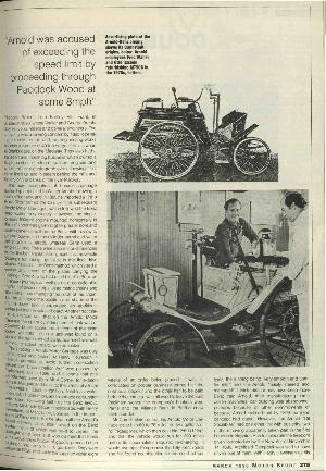
Made from 1896 to 1898 in East Peckham, Kent, England, the engine was based on Benz's intellectual property, a very early self-starting electric dynamotor and flywheel, which acted as a motor to help the car go uphill; otherwise, as a dynamo was a very early form of hybrid car. One car was chased by a policeman on a bicycle and got the first speeding ticket in Paddock Wood, Kent, in 1896, doing 8 MPH when the speed limit was 2 MPH for a vehicle with an engine. Very likely that the engine turned at a constant speed and was set to charge the battery; except when going uphill, it would slow, and the dynamotor would motor and help the car go uphill.
The Arnold Motor Carriage was probably one of the first comparatively safer-to-start internal combustion engine cars. But some other early cars used compressed air for starting and stored enough pressurised air to move the car whilst starting it, I've read. The pictures above right are links from Motor Sport Magazine. Spring starters are still used as an alternative to electric starter motors. I don't think any of the modern types are rewound from the engine, but arewound up by hand.
Electric transmission, but not a hybrid, such as the Owen Magnet car, has no battery, and is a more efficient transmission system than using gears, and is now commonly used on large vehicles such as trains and ships. That is different to what in Britain is called a diesel-electric train, which runs on either diesel or electric pickup.
The first is only the first known; newspapers may exist, or because people passed down memories, drawings and pictures. An earlier EV of 1830 used a primary (not rechargeable) battery.
My father told me that steam, and I thought he said electric vehicles (but rechargeable batteries were not available), were becoming popular during the 1850s, no doubt another variation of motor vehicle history.
Earlier cars, AL-0055-01B, did not have a voltage regulator, but one, two or three current settings, a high, medium, and low switch and the cut-out relay. The cut-out is a rough approximation of the diode rectifiers used in a modern alternator. Circuit diagram created using OrCAD Capture 17, limited trial version. The generator starts because of the little remnant magnetism in the iron of the field electromagnets. The dynamo also had a third brush adjustment of the power produced.
The three-brush dynamo has a simple cut-out-only system. A third brush was used to trim the charge rate and was set differently between summer and winter.
The system is not accurate, and it has a lot of positive feedback, so when the dynamo voltage rises, the field winding voltage rises, and the dynamo would generate even more power when the electrical systems need less power. The battery plays an important part in stabilising the voltage, preventing the voltage from rising.
The dynamo's iron may be sized so that the field winding saturates at, say, 6V, thereby limiting the dynamo's maximum output current, but the voltage would still increase as the engine speed increases; the field current setting and the battery prevent that. The current limiting I described is true of all dynamos and alternators; it is part of their magnetic design.
The field winding fuse protects against voltage and power from running away at the lower current setting. In this case, a 1.5A fuse is probably about right, not the higher values I have found recommended on the internet.
I have guessed the switch connection between D, F1 and F2. By comparison, Ford did not include a dynamo power setting switch before introducing the regulator, but the third brush was also used to change the dynamo power output for summer and winter use. Probably the best strategy is to always run an earlier Ford Model Y car with the headlights on, using the winter setting except when you need to fast charge the battery after starting the car and then only turn the lights off.
Voltage runaway could occur if the battery has become high impedance, said not to accept charge current, and so it is unable to regulate the voltage or accept much charging current. This occurs if the battery is worn out or the acid level has been allowed to drop too much. But I have also found that if the acid level drops and has been topped up with water, the battery's impedance becomes low, and its voltage is very low, until it is charged up. Note that distilled water does not mix with the acid easily, but floats on top, can freeze and crack old-type battery casings in winter.
The cut-out connects when the dynamo voltage is above the expected battery voltage, perhaps 8V; then that current flows into the electrical system, which will enhance the magnetism, keeping the cut-out connected.
The cut-out disconnects when battery current flows back into the dynamo, combined with the battery voltage dropping.
Some control boxes have a third relay for current limiting; I have not seen one of those, and many car makers never included a third current regulator coil, and I don't know why it would be included, because the dynamo is self-current limiting anyway. In any case, lead-acid batteries are best charged with a constant voltage, which is increased slightly when the charge rate is high. That is what the two current compensation windings on the voltage regulator relay do.
Austin Cars - guessing the switch's internal connection. There are two or three current rate settings.
Austin 7's later wiring diagram differs in the power setting for the side lights.
When lights and a high charge rate are required, the side lights are evidently designed to be used instead of the headlights. Otherwise, the headlights should be used.
Side lights are very dim and best only used when parked, as required on a fast road. That is, it is a bad but necessary compromise to drive on sidelights when the higher rate of charge is required. This option is not available on earlier cars.
Earlier Austin 7s, other cars and makes, side lights use the medium current setting. A wire shown dotted is connected between the F1 terminals. So, there was no high charge rate when any lighting was switched on, and there was no power to spare anyway when the headlights were on.
The driver monitors the ammeter and reduces the charge rate when the battery has recovered from starting the car, and the charge rate has died back. The electrical system has no protection if the charge rate is left set high for too long.
The driver needs to move the charge rate switch according to the ammeter, and what inspecting the battery electrolyte tells him. Use a hydrometer, or if the battery needs topping up more often than once every two weeks, or if bubbles form after a long drive, you need to reduce the charging rate. But if there were just one bubble in each cell after a long drive, the charging is about right. [if I remember correctly]. It is necessary to adjust the third brush on the dynamo periodically.
The manual says the ammeter reading should come down to +2A to +4A trickle charge, which is a necessary high rate to compensate for when the electrics are running on battery whilst idling. Therefore, a car, as I said, was only suitable for a hands-on person.
The Austin 7 electric's total power was up to 70W; the dynamo was rated at 6V, 11A, but most other models and makes were rated higher than this, and earlier Austin 7s may have had a lower dynamo rating. The battery was 50AH, probably 300A maximum? Austin car club say 300-400A was the initial current of the starter. This would be the short-circuit current of the battery, cables, and motor before the crank has movement. 100A used to be said for starting; it could not be higher for maximum power transfer, allowing for battery wear when cranking. The coil output voltage is 25,000V or more, but the Austin Manual says 6,000V, no doubt with the spark plug fitted.
Web search tells me that after starting, the battery will demand 30-60A, which will be the limit of the car's electrical system, not the battery. This is not fast charging but normal charging, in which cable and battery resistance can be compensated for, but in a small pre-war car, the dynamo may deliver as little as 2A to 9A.
When I was very young, from 1959 to 1963, I was taken on holiday 250 miles a few times, to Devon and Cornwall, from Kent in an about 1935 Austin 7 and one or both Morris 8s. Mum complained that she had to keep kicking in the footwell of the passenger side to keep the electric fuel pump running on one of the Morris 8s. Later, we went further, but in bigger cars. My father also drove his Ford Anglia to Paris, a similar distance, with his mates. Most cars had worm and wheel, or worm and pin steering box; some had rack and pinion steering and less well-developed damping and suspension, though sport bicycles, of the time, had much better active damping due to their apparent tuning with the cyclist, regardless of his weight, but sensitivity to placement of weight on a cycle rack. Otherwise, the cars have a tendency to wander about on the road like the Austin 7 in this video. The ignition timing adjustment placed on the steering wheel was replaced by about 1930 with the centrifugal advance and vacuum advance mechanisms within the distributor. The second video features a much smarter car, a Riley, but it could be an MG or one of the less basic Morris or Austin cars.
Most parts for cars were made by Lucas Industries - Wikipedia. Ford used its own branding, though it would have bought in parts from other suppliers, as all makers do.
The mechanical cut-out: does not turn on or off precisely; when the dynamo's speed drops, it will draw power from the battery until the holding magnetism drops and the contact opens. It is also likely that the early 4-pole type dynamo produced power even when the engine was idling, so that the inefficient cut-out only needed to close when the engine was running and open when it stopped. The two-pole dynamo is no doubt cheaper to make and replaced the four-pole dynamo in the late 1920s.
The regulator and cut-out:
The regulator is a higher-rated dynamo with forced air cooling, an SU carburettor also fitted to the cheaper Austin and Morris cars, and the switch from cable to hydraulic brakes in the 1930s. These reduce the frequency of maintenance and improve those systems. Battery life increased from 1-2 years to 5-7 years (web search). In modern cars, the battery lasts as long as the car and requires no maintenance, which can be over 20 years. I understand modern cars have electronics such as an alarm that runs and can shorten a battery life a lot; also, software and electronics are developed quickly, so power optimisation and electromagnetic compatibility can be poor. The earliest regulator was used on a car in about 1929, and hydraulic brakes started to be introduced in 1921. In about 1935, both Austin and Morris switched the battery polarity to positive earth; this probably reduced cathodic corrosion slightly of the car's chassis. Riley never introduced hydraulic brakes, switched the battery to positive chassis or introduced the regulator until after 1940. Morris Car Company was owned by Lord Nuffield, but there was an earlier association with Austin, and then Riley became part of the forming group in 1938. The Nuffield Organisation was formed after World War 2 The same as the Nuffield Health Trust charity, although industrial relations might have seemed better, this was because the car companies were smaller and the bosses could know the workers, but they hired and fired workers with little regard for them.
Lower-priced vehicles improved a lot in the 1930s.
The electrical regulator and hydraulic brakes started to be fitted from about 1935, along with a higher-rated dynamo with forced-air cooling. These reduce the frequency of maintenance and improve those systems. Battery life increased from 1-2 years to 5-7 years (web search). The alternator powers all systems when the engine is running, and the battery lasts as long as the car and requires no maintenance, which can be over 20 years in a car made in the 1980s. Although modern cars have alarms and tracking devices, if the parts used in them don't have power-saving modes properly developed in the firmware, they could greatly shorten a car battery's life.
AL-0055-02B vintage car regulator and cut-out, wiring diagram. The component and circuit values differ depending on the car. The three-phase alternator, electronic regulator and rectifiers replaced this type of dynamo, the electromagnetic regulator and the cut-out system soon after 1970.Many more circuits were fused, and relays were added for the high-power headlight circuits.
The addition of the voltage regulator improves the battery charging management. The reduction of four to a two-pole dynamo, which probably occurred in the late 1920s, no doubt meant that there would be more periods when the battery is doing work running the electrical systems and the cut-out, which is not efficient, needs to operate more often. I don't know how common the four-pole dynamo was in earlier cars, but it ceased being made for later cars.
The mechanical voltage regulator is quite good, and the driver did not need or have the option to manage the battery by watching the ammeter and switching the charge rate, but the driver still needs to keep his foot on the throttle when idling in a queue in winter with the lights on. No doubt the newer 2-pole dynamo was cheaper to make, using fewer assembly operations than the early 4-pole dynamo. But the alternator has 12 to 16 poles, and a smaller, faster pulley sweeps about 6 to 16 times more poles per engine revolution and runs all the electrics even when the engine is idling by comparison. The lead-acid battery has been very well suited for many uses since 1860.
Auxiliary equipment became more viable, and A valve car radio of the time may require 6V, 5A (guess), which is more than the ignition system, so by adding accessories, the electrical system current balance could easily be very wrong, particularly if the car's electrics did not include a regulator.
Some cars were negative earth, while others were positive earth. A valve radio could probably cope with either, but other cars used 12V, and this type of radio would not accommodate different battery voltage cars. Heaters in the valves have different current ratings and usually run from 6.3V, but this issue could be resolved.
Car radios could be made of high-quality cast aluminium with compartmentalised sections, a vibratory inverter for the high-voltage section, radio and audio sections, and all had 0V bonding to the case by the shortest path at many points. The valve base connectors had clips. It would therefore be very expensive.
The electrical system of modern cars has a high degree of interference screening and prevention, but at the sources of interference, such as the ignition, motors, and electronics. So that the electrical systems of the car do not interfere with the in-car entertainment systems.
The voltage regulator regulates over a range of current loading and allows the battery to charge as fast as the dynamo can deliver current. But the battery is still used when the engine is idling. The current winding in the regulator applies compensation: a small increase in voltage when the charge current is higher, and a further increase when a lot of electricity is being used, as a compromise to somewhat compensate for when the battery is being run down faster when the car is idling.
The alternator supplies all the power all the time that the engine is running, including when the engine is idling. Consequently, car batteries rarely need topping up and can last at least a few decades, but they still provide voltage stabilisation and some over-voltage protection. The electrical system must work from 5V to double 12V battery voltage, therefore 24V, withstand 60V and very fast high voltage spikes of around 500-800V.
The alternator has no commutator, but the brushes contact slip rings that allow it to rotate twice as fast as a dynamo. When introduced, they were rated at 30A or more, but the Lucas ones, like so many things then, were not well-made at first. They used less material than a comparable but slower-spinning dynamo. By comparison, a dynamo is an alternator combined with a synchronous rectifier, formed by the commutator and brushes. The alternator, as far as I could tell, usually has no current compensation, so the battery is wired from the same junction point as all the other circuits from the alternator and regulator.
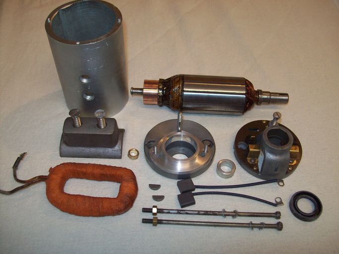
Two-pole two-brush dynamo, thank you for the picturehttps://www.dynamosdynamos.com/ Using just one field coil, as pictured, rather than the usual more efficient two opposing coils. Probably a design compromise so that an increased power dynamo could be fitted. Starter motors and some dynamos have four field coils and four brushes.
Dynamo pictured: -
Notice that the field iron of this two-pole dynamo is solid mild steel, not laminated mu-metal. The switching losses used with a low-frequency switch-mode regulator would be high; consequently, that does not matter, because switching does not occur at full power. Switching losses would occur at a lower power level during pulse width modulation. The high-frequency choke should address the electrical interference. Unless the normal low switching frequency is changed to a very low switching frequency, successfully?
Changing the single field winding to two windings would increase the power output. Alternatively, replacing the field windings with modern high-power permanent magnets should reduce losses, thereby increasing the power further. In this case, the dynamo pulse-width modulating voltage clamp would operate to protect the buck-boost inverter from a maximum of 40V to perhaps 120V.
Post World War II cars also included an instrument regulator which used a hot wire and a bimetallic strip to open a contact when it gets hotter, thereby delivering a regulated mean voltage. It powered the hot wire, fuel and temperature gauges.
Dynamo replacement -
Flash the field winding to ensure that the field is magnetised a little and with the correct polarity. That is, with only the battery chassis cable connected, and the dynamo field wire F disconnected. Connect a wire to the battery live terminal and touch it to the field winding F connection for, say, a minute. This will create a big spark when you disconnect, which will hurt you if you are touching the dynamo field winding F contact; you have no reason to do that. Finally, disconnect the battery, then complete connecting the wiring, then lastly reconnect the battery, chassis cable last. You can prevent the big spark by connecting something resistive, such as a headlamp or stop lamp bulb, across the field winding first; this will prevent compromising the field winding insulation with that high voltage spark, called back EMF, generated.
The regulator's voltage can be adjusted
By moving a screw or by bending metal. This wiring diagram/circuit has two fuses, but 12V instead of 6V before the War, is about what Lucas Industries made for British car makers after World War Two, but before the alternator system replaced them.
Coil winding insulation:
Pre-war, the enamel insulation gets brittle, cracks, and falls off if the wire is moved. Sometime post-war, probably in the 1950s, the enamel was replaced with various types of plastic that do not become brittle. That modern enamel-insulated wire enamel melts and smokes off, so the wire does not need to be scrapped to remove some insulation to make a termination. A soldering Iron may just about be hot enough to melt the insulation of a thin wire.
Replacing electrical systems with electronics to improve a vintage or veteran car's electrical systems.
Three-brush dynamo - The third brush should be disconnected, and the field winding third brush wire connected to the chassis, thereby setting the power to its maximum and removing one brush from the system. Take care of what the brush mounting spring does without a brush fitted. I think the spring without a brush might touch the commutator, which would be a bad thing. Alternatively, set the third brush to its maximum setting.
The electrical system then needs to be switched to negative chassis if it is not already. That is, the battery turned around; any electrical systems that are polarity sensitive, the ammeter and the ignition coil should be turned around. Circuit AL-0060-04 option A fitted can reverse the dynamo and start generating. But the other two circuits require the dynamo to be flashed. Circuit 01 must not be connected, but circuit 02 can or should be connected to the Chassis and Field. It will then stop a high-voltage spark from occurring when you disconnect the battery from the field contact of the dynamo.
A college tutor characterised student nature by saying, "If all else fails, read the instructions" Installing the unit could still go wrong, and parts can be broken, instead of fuses breaking.
Switch from a 6V to a 12V electrical system.
Circuits -02 and -04 have settings to accommodate three of four combinations of 6V and 12V dynamo and battery voltage. The combination, therefore, of a 12V dynamo to 6V electrics would not work at low and modest RPM; this setting probably should not be provided.
Dynamo and battery charging: The boost-only switch-mode regulator diagrams are PDF AL-0060-01 and AL-0060-05, which use electronic components rather than a microcontroller, which shows the software functions that need to be created. The second and fourth sets of circuit diagrams, PDF AL-0060-02 and -04, I have not chosen a suitable microcontroller, but many modest-speed 48-pin types will work well. It is best to avoid using a multitasking operating system, but write software and interrupt handlers. The second circuit, the buck-boost regulator, is the best option, but making PCBs with provision for a small number of different components for either 02 or 04 circuits could be included on the PCB, but not fitted, which of those different components, depending on which circuit you choose to make.
The final version AL-0060-04, which I have included other partly worked-out solutions for are almost identical, but for some unintended differences in where the Vboot+ net is either rectified dynamo output or after the buck-boost or from the battery rectified. That is, after splitting -04 away, they then became more similar as I continued to develop both, plus I discovered the better SPV1040 start-up boost IC. Buck-boost ICs vary, and finally, I have worked on those that look promising, and I compare their merits.
AL-0060-01A dynamo manager, Boost Regulator to extend low RPM operation; this is a 6V analogue partial solution. The current sensor at the dynamo is used for maximum power transfer optimisation. In this circuit, the setting has to be found by trial, measurement and adjustment. That current sensor is also used to provide battery cable resistance compensation and switch-mode power supply current feedback. The boost circuit requires a slightly higher RPM to start up; then it will operate at a lower RPM than the dynamo system would normally. CADSTAR 18 used. The circuits are draft, and some of the component values are incorrect.
The circuits have screening and over-voltage protection measures. With or without these circuits, the car should not be run without the battery connected; the battery stabilises the voltage in both cases. It is possible that these circuits will run without a car battery, and the compensation should be set to accommodate all loading conditions. The changeover relay selects between the field-winding power source, the PWM regulator or direct connection to the dynamo for starting power generation. This will start without the battery, such as with magneto-electrics and would introduce a more certain power generation start-up because there is no semiconductor voltage step to overcome before the field winding is powered.
Circuits AL-0060-02 and higher should work without a battery fitted, although they are not designed to work that way, and their output will drop briefly with load increase.
Electronics mostly start up above 3.5V, but the dynamo may produce less than 1 or 2V from the residual magnetism, so the field winding is connected by a relay to the dynamo initially. When the dynamo is generating more than about 3.5V, the Field winding current is controlled by a pulse width modulator (PWM) to regulate the dynamo output voltage.
AL-0060-01A Field winding power and dynamo regulator. The field is turned off whilst the dynamo output is over-voltage clamped; therefore, when the clamp is lifted, the field is briefly turned on, though it should not be until the dynamo voltage has had time to resettle again and be measured.
This does not provide any more power for the car's electrical systems at high RPM. At low RPM, the dynamo will not start producing power, but as long as the engine has been running at a moderate RPM and the dynamo has started up, it will continue to produce a little power at a lower RPM with this circuit that was not provided by the original electrical system. In addition, this circuit clamps the dynamo voltage using 10mS PWM so that the battery is also not severely overcharged. This still does not resolve all issues, but using LED lighting will help by reducing the power required.
Because of the relay, the dynamo will start up even with a flat battery in a car with a magneto. In case of faulty wiring, the fuse should blow before any semiconductors are broken. The field should be flashed with the cable from the unit disconnected; this is different to circuits -02, -05 and some of the variants of circuit -04, but the same as the original electromechanical system.
But because the battery is connected to the output, if it were to become flat and low impedance rather than high impedance, this will stop the charging system from starting up.
Summary of this circuit version 01
This circuit does not start generating at a lower RPM, the extra power region I describe in the graph further below, but it will continue to generate power in this extra power region once it has started generating at a higher RPM and continue to generate until the RPM drops to such a low RPM that not enough power is produced to overcome all losses and deliver 7V to the field windings, with the boost SMP running.
The over-voltage protection, which will operate a lot when speed increases or when lighting is turned off, will put the input capacitors under more stress. By comparison, circuits -04? (buck-boost) and -05? (boost) have a separate power recycling transistor to put the excess power back into the dynamo.
There are, of course, losses in the system, so the charging system will stop producing enough power for itself when the RPM has dropped to where the dynamo cannot produce more than 100% of what the field requires. This is better than the original system, where the field only ever got 20%, perhaps more of the total power generated, so the dynamo would have stopped generating at a higher speed.
This circuit does not have the buck converter that recovers more of the power that is normally returned to the dynamo at higher RPM. So, with all electrical systems running, the battery would be trickle-charged, not the usual fast charge that occurs after starting up without the lights on and high charge selected or what the regulator does. Changing the lighting to LED lighting may reduce the power used and resolve this issue with this circuit.
Rewind the dynamo armature to a higher voltage and use a higher-voltage-rated buck regulator to drop to 6V or 12V for the field windings, battery and the electrical system.
Simpler, more efficient electronic regulator. Because it only has to step down.
An overvoltage clamp circuit is required.
But the dynamo electrical system becomes non-standard, though and could not be put back to original conveniently.
Using LED lighting will boost the light level and reduce the current taken, but an automotive unit can include a power-wasting load, so that the unit matches the load of a filament lamp unit.
You may be able to remove the dummy load, which is a bank of resistors. The electronics should still operate properly. That is, if one LED fails by breaking the open circuit, then all the LEDs of that circuit are turned off, which would, on a modern car, illuminate a dashboard warning light. But you may need extra electronics to pulse-width-modulation drive the red stop/taillight function. The PWM is either 100% for the stop light function or 5% for the taillight function running at 100 Hz.
The taillight function cannot be created using a series resistor; even if the LEDs were to illuminate, their colour may not be legally correct. On the other hand, all 12V car systems, including the lighting, should work down to 5V but not at their correct intensity.
A 5W LED can be equivalent to a 50W filament bulb. An Austin 7 was fitted with 18W headlamp bulbs. Other bulbs are 3W but would be 5W or 20W for indicator lights now; these probably would not reduce as much as 90% using cheap LED units, and less wasteful units are probably not available.
The LED drive may be by a linear current source; therefore the efficiency could be reduced to 25%, or perhaps by a switch mode power supply, in which case the efficiency may be 80%. Either way, LED lighting is beneficial for saving power.
If, by this change to the lighting, enough power at higher RPM, there is no need to proceed with the buck-boost regulator below; a boost-only regulator may be adequate. You could try it using one of these boost regulator IC demonstration kits:
MP3433, 22V, 20A, no evaluation kit, will start up from 0.8V with an external 2.8V to 22V. It also includes a high-side low-loss diode function. The diagram on the website shows two audio inputs, CHL and CHR, that increase the output voltage when sound is detected. Monolithic Power Systems
MP3435, 19A, 22V. There is an evaluation kit, 3V to 20V, which also includes a high-side low-drop diode function.
Or MPT612; NXP includes MPPT software for this microcontroller.
Most boost regulators or a microcontroller plus an SPV1040 to provide start-up power.
Limited function, minimal circuit: AL-0060-05A (PDF) Boost SMP evaluation board. This has a much better over-voltage clamp, which does not put a high ripple current into the capacitors. But it is only rated at 20V, so it may fail on a 12V system, but be just about okay for a 6V system.
--------------------------------------------
Buck-Boost Switch-mode power supply to provide more of the available power: -
The Dynamo's power output can be at least tripled at high RPM and start producing power at a lower RPM without having to have been running at a higher RPM prior, unlike circuit 01. As in the previous circuit, the power available remains the same at the stated dynamo rating and RPM.
When an auxiliary electrical system is turned off, the dynamo will continue to generate a surplus of power for a few minutes. The dynamo voltage will rise; the buck regulator will reduce the dynamo current. If this voltage becomes too high, an overvoltage clamp operates using 10mS pulses, shorting out the dynamo. This protects the buck-boost electronics and returns potential extra power back as motive force. That is, the dynamo motor's a little, so it takes less force from the engine. Which is similar to what would have happened, except that the battery would have had to absorb some of that extra power.
Whether a unit is home-made or manufactured, this would be an after-market product, so it does not need to comply with each of the different manufacturers' own standards that they impose on their suppliers. It needs to work with double battery voltage, 12V on a 6V or 24V, on a 12V car electrical system.
The voltage control response time is slow because of the magnetism stored in the iron, made slower by the diode across the field winding, so the dynamo output crowbar will necessarily do more work, consequently. That is, the crowbar will operate normally when driving the car, and auxiliary circuits are turned off.
But the average field voltage must be limited to the dynamo's original rating, 7V or 8V. The third brush adjustment is set to maximum, or reconnected to chassis 0V, to feed the field winding up to its maximum rating.
Other models and car makes used up to about a 125W dynamo; some were 12V. Post-war, 1945, dynamos increased to 400W, and bigger cars had higher wattage dynamos. Subsequently, alternator power and more electrically driven systems have caused the power budget to increase.
Convert a 12V Dynamo's output to 6V. And the extra power at low RPM is not available.
Boost-only regulator circuits -01 and -05; the output current would be half its expected value until the dynamo reached over 2,000 RPM.
Increase the 6V dynamo to 12V electrics.
Run a 12V dynamo and 12V car electrics.
Using the microcontroller and software buck-boost converter is likely to have poorer efficiency than using a switch-mode converter IC, which will also include the four MOSFET drivers and MOSFET switching tuning to minimise switching losses.
AL-0060-02A dynamo manager,Buck-Boost Regulator to extend the low RPM operation - 6V or 12V or combination solution and fast charging with lights on, if necessary, at higher RPM. CADSTAR 18 was used. Some of the components and their values are not resolved yet.
This is not quite an interleaved dual-phase, but it is dual-phase, and it shares some of the reduced EMC benefits. Another sheet has the second phase; it is a partial duplication of this sheet. A better EMC profile may be achieved by using one of the Buck-Boost ICs with extra features for EMC and efficiency. The microcontroller is still used to optimise the power transfer and the field PWM control. There would be benefits in changing to GAN MOSFETs at a higher operating frequency, reduced gate switching noise, and reduced PCB size.
Parts of the Field drive circuit sheet are similar for both the boost-only and the buck-boost circuit.
It took a while for me to work out this function, for which I have a few good, simple solutions.
The Bipolar Junction Transistor (BJT) solutions have less protection, but it should be enough normally. A variant need not require a battery, but won't start up unless the remnant magnetism is enough for the dynamo to produce 1V.
The electromechanical relay will blow fuses if badly wired, but it is a better solution, starting up from a fraction of a volt out of the dynamo.
Two MOSFETs back-to-back resolve most protection issues. It may run from Dynamo power or battery power via the ignition circuit. Still, in any case, the field winding power comes from the dynamo's remnant magnetism in the field iron. See my draft CoolGAN bidirectional MOSFET switch circuit AL-0060-03C
The Boost regulator is good because a few solutions will start up from about 1V and then power the main buck-boost boost regulator. But the best is that SPV1040 solves most issues: it operates from 300 mV to 5V, powers the microcontroller, and starts up from < 400 mV using dynamo remnant magnetism. That is, it should work reliably with a lower-voltage 6V system.
European manufacturers such as STM or NXP answered in English comprehensively, such as on the auxiliary boost regulator.
That is, if the battery is flat, the dynamo should start generating if the car uses magneto ignition. Consequently, the dynamo will start up and run somewhere in what I describe as the extra power region of the graph, further below.
This circuit 02 has now been developed further.
The cut-out function is more precise using a rectifier diode.
It will start generating power at a lower RPM or start up more quickly.
This circuit, by default, does not remagnetise the field negative chassis, unlike circuit 04.
If it is necessary to reverse the car's electrics, including the field windings, the unit should be connected to the chassis and the field first, at least so that the snubber diode protects the field winding and the installer from a high-voltage spark when the field is disconnected from the battery.
A disadvantage is that more parts are required to provide functions that are integrated into Buck-Boost ICs or modules.
Circuit 01 should be put aside.
AL-0060-02A There is now just one field driver; it uses power produced by remnant magnetism in the dynamo's field iron, which is boosted to a usable voltage for the microcontroller, main boost regulator gate drive and the field driver switch. The start-up is different to the first circuit, because all the available power is used to power up the field more quickly, and the field PWM is set so that the field just gets up to the maximum available. It starts up in the extra power region when there is adequate power available in the dynamo.
This circuit is reasonably well protected and should withstand flashing the dynamo and prevent arcing that would compromise the winding insulation slightly. The "5V0start" net powers the microprocessor and then contributes to the power for the gate drivers. The Field winding PWM is set to take less than what is available. The over-voltage clamping function protects the circuit. Otherwise, the over-voltage clamp function should not be needed often because the buck regulator mode accommodates some variable voltage. Reducing the PWM field frequency will reduce losses in the iron in the field, and the buck-boost can accommodate the fluctuation, provided the field current is set to produce at least enough power.
st.com community advised me that I could reduce R1 and R56 to 2K. I have reduced to one 2K2 resistor, which improves the gate drive over using higher-value resistors surrounding the SPV1040 boosted supply. I have also added a diode between Vdynamo+ and Vboot+ nets so that the dynamo output can continue to increase, but without using the start-up boost supply or needing to supply the car electrical system at the same time; this diode is not beneficial (this came from circuit -04) when the battery is in good order.
No power is taken from the ignition circuit other than to run the status LEDs. The Red/Amber/Green LED will flash slowly as a warning, not a fault, if the battery deep discharge recovery feature is turned on, but that feature only doubles the battery voltage, which does not go any higher, but at a very low current <0.5A. So normally the battery and other circuits, if used, take more power, and the voltage drops to 7V or less if that is as much as the dynamo can deliver optimally.
It took me a while to develop the Field Drive function. Here are some alternatives that may have weaknesses: AL-0060-03B. A problem arises that the dynamo will not generate unless D and F are connected together at start-up, but there is little voltage generated by the dynamo for the electronics to start up and turn on the connection. The relay in AL-0060-01? resolves this issue, though it will build up power slowly, just like a car's standard system would anyway. The electronic boost regulator increases the voltage to 7V and drives the field winding with up to 100% of the dynamo output. The voltage, therefore, builds up more quickly if the dynamo is rotating fast enough, but it will start generating at a lower RPM than the original system could. This is the extra power in the graph below: the anticipated advantage of AL-0060-02a, or AL-0060-04a. When the dynamo is running in its extra power region, it generates a surplus that is delivered to the car's electrical systems sooner and at a lower RPM.
A 6V dynamo will produce about 1V from the remnant magnetism in the iron of the field magnets, which is used by the start-up circuits to power the microprocessor and the status LEDs. The SPV1040 boost regulators listed below will start up at a low enough voltage to be relied on to start up on a car with a magneto and a flat 6V battery. The complication, though, is that these ICs only produce 5V, so I have included a circuit that only takes pulses of current on the forward conversion cycle of the IC using a voltage multiplier diode-capacitor network, but with an output resistor.
A flat battery can be high impedance and can be recovered by the deep discharge recovery method by charging it from a high voltage, say 5 times the battery's rated voltage, until it starts to draw current, which may happen after many hours. I have not included this option to restore a deeply discharged battery.
If a flat battery is low impedance, which can also occur if the acid level has dropped a lot, then it's been topped up. Then, putting some current into it will restore it again. But if a plate has buckled and shorted, then the other cells will produce a lot of hydrogen, which is dangerous.
Boost regulators that start up from a lower voltage but only work to the lower 5V. That may have other features, such as MPPT managers.
SPV1040 0.34V to 5.5V may start at 300mV (voltage increasing to 270 mV, voltage decreasing to 140mV).
SPV1050 0.58V to 5.5V <70mA or buck-boost from 2.8V to 18V <30mA has many other features. Boost works down to 150mV after starting.
bq25570 0.6V to 5.1V works down to 100 mV 110mA includes a battery charger.
LTC3105 1.1V to 5.5V. but not start at 225 mV - 400mV due to #shutdown threshold of 1.1V.
AP3015 or AP3015A 1V or 1.1V to 12V then shuts down <0.25V 70mA or 300mA 38V out.
The MPPT function ensures the boost regulator starts up without stalling, trying with a very low start-up voltage. st.com calls the MPPT strategy "The perturb and observe algorithm is based on monitoring either the voltage or the current supplied by the
DC power source unit so that the PWM signal duty cycle is increased or decreased step-by-step according to the
input power trend." Introducing a slow voltage ripple and recording the highest power transfer dynamo voltage for a given current, and making a small adjustment to a characteristic table. so that the optimum power characteristic curve is improved and adjusted for brush wear and temperature.
Permanent magnets to replace the field windings.
The field could be continually magnetised using modern high-power permanent magnets. The over-voltage clamp function will then regulate the output voltage using PWM running at 100Hz. These circuits accommodate this option. You leave the field winding's output disconnected. The status LEDs will not indicate differently.
Resolving poor switching efficiency in the circuit -
The microcontroller circuits can do all that is required, but the switching needs to be optimised, plus there are many ancillary parts that need to be included. I have shown power transistor switching optimisation in my blog Electronics-high-frequency-arc-lamp, in one instance, which improves the efficiency greatly by tuning the switching time using simulation for one ideal situation. It is unlikely that transistors will match the models, so more cooling than a modern power supply would be required. This arc lamp power supply was reliable, and the simple regulator gave a good lower flicker light than a traditional ballast unit, which was much more important than better efficiency.
I partially developed the following circuits a little beyond what I would normally do in order to illustrate the benefits and disadvantages of each buck-boost controller IC.
Evaluation of various buck-boost controller ICs.
The field windings can be powered from the battery, which will reverse the dynamo polarity if that is required, as part of how it works. The circuit using MAX20048 that uses a relay should not be flashed, which is not required because the battery is used to start the dynamo generating, which puts the dynamo's magnetism right. The LM51772 circuit can be connected and requires the field to be flashed. The other circuits can be connected whilst the field is flashed, but they don't all require to be flashed; those circuits magnetise or re-magnetise the dynamo as part of normal operation using the battery or remnant magnetism in the dynamo. Cars with a magneto ignition may be started even if the battery is flat. A deeply discharged high-impedance state battery should be recoverable, though impractically slowly; by comparison, the original system would probably blow light bulbs and the field fuse.
The design AL-0060-04B encompasses AL-0060-02A but uses a buck-boost controller IC or modules rather than requiring software to be written. The unit also has a USB charging port, which activates when the dynamo is producing surplus power. Other features could be provided via the USB port, which is connected to the microcontroller.
Selection of buck-boost converter IC or Module:
Likely buck-boost modules or ICs that may suit, with some additional circuitry; that is, most of them need to work off spec. But not out of spec. But the detail is not in the datasheet or available by support request to people without a company email address. In most cases, the input start-up voltage is below IC spec but easily within the power MOSFET capability:
AL-0062-03A ISL81601 Buck-boost IC. This SiMetrix model is adapted from a working example, but now it does not work. There is no SiMetrix model for the ISL81401 Buck-boost IC that I have selected and offered. A short initial period of operation in the forward direction from the battery to the dynamo is required before it operates in the reverse direction from the dynamo to the battery normally. This simulation is for Renesas' version of SiMetrix. But at startup, the power briefly goes from left to right, then switches to normal operation with power flowing from right to left.
Unfortunately, supplying a 5V from the boost supply to ExtBias pin does not allow the IC to run at lower than the specified Vin 4.5V say 300mV. But the IC also operates in reverse direction and can use the battery or axillary small boost supply to start up and run from a very low voltage from the dynamo. This is described by application note on the IC using it as an uninterruptible power supply using super capacitors that discharge down to 0V.
This power supply therefore cannot start up using dynamo remnant magnetism, unlike circuit -02 above. In this case it relies on the battery in order to start up. But a low power dynamo might be started up using the SPV1040 boost regulator to power the field so that second boost supply is included on the circuit, this would be beneficial on a car with magneto ignition and the battery was flat.
DE means Discharge Emulation. This mode is not used therefore FB_IN must be above 300mV and below VCC5V.
DE also mean Diode Emulation. The datasheet has a number of confusing or missing details but if DE has this meaning it would be useful but whether it is available in reverse mode is unlikely.
I read in Renesas support community that the IC must run in forward direction remain enabled before it will run in the reverse direction required. An application note describes using the IC for UPS with super-capacitors operating in reverse down to nearly 0V.
FB_IN is now battery output is driven high and FB_OUT which is Dynamo input is low unless the dynamo voltage is ~30V so that the buck-boost starts up driving forward mode (Battery to Dynamo). The FB_IN and FB_OUT are then driven on and off respectively and the battery starts charging from the dynamo. The controller must run for about 1.7mS (so 2 or 3mS) in forward mode before it is switched to reverse mode.
But it won't start unless the battery is at least 4.5V so if the battery is low or flat an axillary boost regulator from the dynamo powers VIN which forces Boost regulator. The Buck-boost won't be able to run in buck mode until the battery voltage has charged to >4.5V. Then it can run as intended generating extra power.
EN/UVLO Enable pin is driven true (~2V) when the voltages are right to start and driven false when the dynamo is not generating power, this also ensures that the battery is not discharged.
ExtBias - may provide 4.8V - 5.2V from 5V0start or it might power the Gate supply alternatively VIN will do that. The threshold is over 4.8V so what it does is marginal. consequently, it might be better to connect ExtBias to 0V. If VIN falls but remains above 3.5V and ExtBias is actively supply gate drive, then the buck-boost will work to a lower voltage. To find out which is happening measure VDD
IMON_OUT is set by resistor to a low current limit but just enough to just cause initial forward current to flow. Assuming that is necessary? The current tolerance is wide. I don't know if the controller will start up forward mode but set to zero current limit by not fitting the resistor?
IMON_IN is set to protect the MOSFETs, the maximum power transfer, and the current is limited by soft clamping, pulling the COMP pin down by a microcontroller DAC port and a diode.
The current monitors need to be calibrated periodically by driving both FB_?? high to turn the drive off whilst the actual zero current signal is recorded.
The peak current limits are a little lower in reverse mode, and the average forward current is set by an external resistor low used briefly at start-up.
That is the plan, but I have not demonstrated it by modelling it.
This group of ICs may or may not be able to operate in parallel with another of the same ICs, interleaved clock, and in reverse?
Connecting most of the analogue pins in parallel is not the method recommended with this IC. Therefore, this is not possible; consequently, using one FB_IN pin for voltage feedback and the other FB_IN pin is connected to 0V to enable a 180' clock output.
ISL81601 IC looks like it may be a better option for synchronised and coupled status signalling between two or more phase-interleaved modes of operation.
The balancing of the current between the different phases is more complicated than other ADI ICs and requires op-amp circuits to share the power by driving the Feedback pins.
Therefore, the dither function is available to improve the EMC profile instead. I've been advised to take measures to prevent high di/dt rates when the battery is connected, and I have included large input and output chokes.
The SiMetrix simulation is for ISL81601 only. But there are differences between the ISL81401 and the ISL81601, with tolerances considered. Such as;
ISL81401 IMON_IN and OUT maximum current set resistor is 41K (offset 1.2V / 29.0uA).
ISL81601 IMON_IN maximum current set resistor is 53K (offset 1.2V / 22.5uA).
ISL81601 IMON_OUT maximum current set resistor is 54K (offset 1.2V / 22.0uA).
Use the EVB test these options. The EVB can output up to 8A.
I have drafted a circuit that uses the axillary 5V boost regulator to trick the ISL81401 to start up even if the battery voltage is below 4.5V. Consequently, the regulator will run in boost mode even when the dynamo voltages is really higher than the battery and buck mode should be used but, in any case, the battery will be charged slowly until it reaches the right conditions and VIN becomes the battery voltage rather than the boost 5V.
There are some useful features.
VIN is linked to the under-voltage sense and supplies the internal LDOs. Although I have added a changeover switch, which is like a diode, so that VIN is powered from 5V boosted from the dynamo, just to get the IC running and the battery charged enough for the IC to work normally in reverse mode subsequently.
EXTBIAS can be used to provide the switching transistors with a higher 8V gate drive. Or the pin can be connected to 0V.
VDD of 5.3V is used for gate driving.
VCC5V is probably cleaner, better for the analogue electronics.
FB_IN is coupled to the battery output, but in case the battery is flat, the processor DAC pin VFB_DAC must be driven high enough to ensure FB_IN > 300mV so that reverse operation is enabled.
IMON_OUT and IMON_IN measure the input and output currents, where 1.2V is the current limit. They must be buffered; then they can be connected to the microcontroller A/D inputs.
Their outputs are offset, so a little negative current still appears as a reduced output source current.
The current limits can not be set from the microcontroller ports easily because variable resistors are required. Control is by the comp pin to manage power output.
The input is offset -80mV to 150mV at CS, for example.
The two current sensors have a common mode range that includes 0V to +40V.
60' or 120' clock options are not available, and the 180' clock two-phase interleaved clock is also not available.
PGOOD is not used.
MOSFET power switching optimisation - The gates of the power MOSFETs must not include series resistors so that the switching optimisation circuit can operate.
There are simulation models available, but they are difficult to find, and you need to register using a company-like domain email address, rather than a general email like Gmail. address. https://www.renesas.com/us/en/products/isim.html
The battery voltage must be greater than 4.5V and be connected to VIN for the buck-boost to work; it then works in reverse. FB_IN monitors the battery, which must be greater than 300mV and less than VCC5V, which, in any case, it must be. Therefore, diode emulation mode is not available.
Constant current limit mode rather than hiccup mode; this is done by placing a resistor from LG2 to 0V of about 20K.
But I have not been able to get the simulation to run, either with or without power control by driving the FB_IN pin rather than the COMP pin.
Pros and cons:
Requires the battery to have a little charge and probably would not increase the voltage enough to run the field winding starting from a flat battery. The relay start-up for the field circuit taken from other circuits could resolve this issue.
The current measurement is not accurate. An automatic zero and scaling procedure needs to be done. The microcontroller's ADCs are accurate enough and are referenced to the 3.3V supply. But the current measurement used to turn off the field current when the dynamo is not generating enough power is not accurate.
Once the starting procedure is followed, the buck-boost will continue to operate down to nearly 0V. Although it will probably stop providing enough power for the field at 2V or 3V. The battery probably needs to be charged to at least 5V for full buck-boost operation to work, depending on whether ExtBias can be used.
Their support will reply to some questions, but they may not reply to follow-up questions.
MAX20048 2V (4.5V) to 36V EVB £230, up to 16A input, 5A output. £8.40
AL-0061-02A Buck-Boost:the LTspice model. If it is accurate, this integrated circuit is different to other buck-boost ICs. The IC requires 4.5V to start, then continues to work down to a 2 V input, so it cannot be used to start from remnant dynamo magnetism, which is only up to 1V or 2V. Once running, it continues to work down to 2 V and generates its own 5V Vcc for gate drive.
LTspice 24.1.10 for Windows 10 or 26 for Windows 11; earlier
version VXII may also be suitable and will run on Windows 7.
Unfortunately, on a Windows PC that does not support LTspice 26, you cannot let it update
Therefore, the libraries cannot be updated either.
Blue Vi - Dynamo voltage. The rectified voltage rises above the dynamo voltage to 21V during the start-up period, 10mS for ~1.7 ms, using power drawn from the battery.
Red Vout - Battery voltage.
Pink - compensation pin. I have not optimised the compensation, so the waveforms look thick due to instability. It turns out that when the input voltage and power drop to zero, this pin's voltage is raised a little by a small current from the battery until the EN enable pin is held low, to stop it taking battery power when the dynamo is not running.
Grey Ven - enable pin. This pin needs to be pulsed or pulled low to stop the IC from taking power from the battery.
Green I(Vi) - input current after the rectifier. An additional circuit simulating the microcontroller reduces the power drawn from the dynamo when the input voltage is 2-3V to prevent the controller from shutting down.
Emerald Green I battery - output current. Is briefly reversed after ~6 ms. If the battery voltage is higher than the set point, the current does not reverse in this controller, in comparison with other controller ICs. There is a small current drawn from the battery when there is no power input until the controller IC's enable pin is pulled low.
To repeat the point - The controller needs to be disabled when the dynamo is not producing power otherwise once running it will continue to draw current from the battery.
It seemed that the IC cannot be tricked into starting up using a boost regulator from 400mV Vin, but it turns out that it takes a long time for the model to simulate and it needs to run for 10mS which in real time is very much longer before it has completed its start-up period. That was putting 4.5V on pins IN and OUT and also ensuring CSP1 and CSN1 are less than 300mV above IN, the datasheet says VIN but there is no VIN pin.
Partly developed circuit and PCB: AL-0060-04B buck-boost MAX20048 has about 222 components but with the auxiliary boost regulator instead of the relay has about 250 components.
Pros and cons:
This controller can start with a flat battery, provided there is some remnant magnetism in the dynamo.
The current measurement is not accurate. The system needs to be calibrated by driving at maximum current with the field at 7V, then scaling the current figure from 7V divided by the measured dynamo voltage. This needs to be done at a few points because the scaling and the zero are imprecise. The microcontroller's ADCs are accurate enough and are referenced to the 3.3V supply.
Once the starting procedure is followed, the buck-boost will continue to operate down to 2 or 3V. Although it will probably stop providing enough power for the field at 2V or 3V.
Their support forum probably won't answer your questions, but their webinars may do, and their LTspice models are particularly flexible and will safely give you a feel for any manufacturer part you choose to simulate.
MAX20048 uses an auxiliary boost regulator instead of a relay. Not recommended.
This variation uses the auxiliary boost regulator from the dynamo if the battery is flat rather
than a relay to start up. But the boost regulator is low power, so it is only likely to work with a low power dynamo. It uses the battery if its voltage exceeds ~3V to power the field. The MAX20048 can
start up from >4.5V and the system will run normally charging the battery. The partly developed circuit: AL-0060-04B buck-boost MAX20048 Boost
MAX25431 6V 36V, EVB is £120 initially start 7V, 3-25Vout so is not suitable £1.80
LT8708 Has a bidirectional control logic input. Requires a 6.4V supply, then runs from 2.8V, 80V max. I have not evaluated this IC.
LT8708-1 Slave multiphase for LT8708.
LT8390A 4V min, 60V maximum. Has Vout disconnect and spread spectrum. I have not evaluated this IC.
LTC3789 4V 38V £12, EVB 25A 6 to 36V DC2253A 2 phase interleaved. $229; there is also a single-phase 12A EVB.
AL-0061-01A Buck-Boost LTC3789 LTspice 24 or 26 simulation. PDFs ofDiagramPlot. Don't take too much notice of the section of instability. You can see that if the battery voltage is high, power is taken from the battery to produce a rising high input voltage until the run is stopped. starts up and runs when Vin is >3.4V to 4V; that is, D5, D7, and D11 are not fitted, and VIN is connected to IN+.
The LTC3789 can be tricked into starting up from a lower voltage by fitting D7, but it may not be operating properly.
The LTC3789 can be tricked into continuing to operate down to a lower voltage by fitting D11, but although it looks okay, it is operating outside its datasheet specification.
MOSFET switching optimisation
It is most likely that the IC would not run its normal initialisation to optimise the switching of the power MOSFETs if tricked into starting from a lower voltage?
Alternatively, the IC may adjust whilst running anyway, and nothing further needs to be done.
Putting auxiliary 5V into VIN works in the simulations. No doubt because vinsns and voutsns are connected correctly, buck and boost modes are determined correctly. It may therefore be wrong to consider these alternative connections a trick. In other words, without a positive support reply, testing the running in an EVB might work out okay, but a different part should be evaluated.
This IC should work well in a 12V system, but would not offer much extra power at low RPM in a 6V system.
This controller is potentially one of the lowest electrical noise if configured dual or multiphase, would operate in a 12V system only and requires battery power to start up.
The circuit is unlikely to start up in this configuration.
LTC3779 - offers no reverse current drawn at start-up and 150V operation.
LTM4712 5V 36V 12A (Vin or Vout) £44
Works with low voltage input, provided that an auxiliary 5V power supply to EXTVcc and rectified dynamo input to VIN. Unlike LTC3789 there is no need to work around anything to get the IC to operate with a very low input voltage in the LTspice. But doing so is not covered by the datasheet. That is the axillary supply needs to be greater than 4.6V and below 14V then the module functions.
This module, therefore, is only fully useful in a 12V electrical system, though it will work, but without producing any extra power at low RPM in a 6V system.
LTspice model consume a lot of current (20-28A) as it starts up, briefly probably so that the power transistors drive is optimised. When adapted to current limited and rectified input voltage the simulation works up to a point where the simulation runs so slowly that it does not complete. There is always a smaller current pulse taken for a millisecond from the battery then subsequently the cut-out function prevents that occurring.
These simulations did start to run from very low input voltage but not properly.
EVAL-LTM4712-A2Z four modules 48A for £160,
EVAL-LTM4712-A1Z two modules 24A out. £142 + VAT.
These EVBs - may not be possible to wire them so that one current monitor is connected to the input and the other connected to the output. I don't know if it would be possible to power VIN from auxiliary 5V and power EXTVcc from the input supply? My support question did not get answered.
The field winding cannot be taken from SW2 pins and rectified, but the pins are output so that an snubber R+C can be fitted. (TP15, 28, 36, 44).
LTM4712: none of the model's complete operation other than the original model, and that has very high current >20A taken during start-up for 1 or 2 mS. This model does not include low-voltage start-up but starts from about 5V, and then shows unintended reverse operation, which must be disabled to prevent battery power from being drained and the input voltage from rising and causing damage. The simulations do not demonstrate full function.
These models attempt to start up with an out of spec low voltage but don't run;
AL-0061-03A ltm4712 buck-boost - op current Battery mppt.asc
These models run okay then run so slowly that they virtually stop after 2 or 3mS. RUN and EXTVcc are enabled and powered with VIN at a fraction of a volt.
These models are operated within datasheet or slightly wider spec. based on ADI models;
These models (-1) do not support very low voltage start-up, but shows the current limiting Maximum Power Point Tracking working after the simulation has run for a longer time. The reverse current flow battery to the input occurs until the RUN is driven false.
Starting the IC from low voltage and current question to the support forum did get answered, so using an EVB is a good strategy to test start-up operation. It probably should not be done in any case.
MOSFET switching optimisation
It is most likely that the modules do not run their normal initialisation to optimise the switching of the power MOSFETs, so after the dynamo is running, disable and re-enable the IC to get it to initialise properly within the specified voltage range. Possibly sequentially?
Alternatively, the modules may adjust whilst running anyway, and nothing further needs to be done. In any case, the module is not being tricked into working, although this very low-voltage start-up using the EXTVcc is not illustrated in the datasheet.
These buck-boost modules run bidirectionally. If reverse current flows from the battery, the rectified input voltage rises, and the module's RUN input must be set to False. This occurs if the battery voltage is higher than the set voltage. The condition is detected by the rectified input voltage rising above the dynamo output voltage or the current direction being reversed. The output current direction can also reverse briefly if the battery is supplying the field current, but this should not be allowed to continue either.
These controller modules are potentially the lowest electrical noise option because all the power switching is within the module. A car, and more so a vintage car's electrical system environment, will have a lot more electrical noise.
Would only operate in a 12V system and requires battery power to start up. And there is no certainty that it will start up in a 6V system.
ADI support forum did not answer my questions, but the datasheets and LTspice models work, giving a good understanding of what the parts do.
LM51772 is suitably wide -40 to 125 °C. 0V to 55V with 3.5V bias I2C interface £7.30, EVB available for £212.
or LM51772-q1, which is automotive grade.
Current limit is settable between 5mV and 70mV with 1% accuracy and 2.5uV offset, 2.8V to Vin. Consequently, it can not be used to limit start-up current, but it can be used to manage the cut-out function and to limit the output current to 2.5A to 35A, say. For starting up at a low but maximum power, the COMP pin should be driven by an open-drain variable voltage clamp.
Cable compensation may be useful from the optional current sense input if it is placed on the output, which I guess might be the only place where current sensing will be useful. But I don't think it can be set by programming through the I2C bus; a resistor has to be used; therefore, the function is probably best not used.
BIAS alternative power for internal circuits and Gate Drive, said to be from 3.5V, but power MOSFETs need ~5V drive.
Vin sense 0 to 55V, Vout sense 1V to 55V.
Under-voltage range falling from 2.8V to rising 3.5V
Output discharge - may not be possible to turn off? But can be set to 25mA, the lowest setting *** this needs to be resolved? ***
This controller is bidirectional - I do not know the best way of inhibiting this function, but disabling it should work because it should also start up on low input voltage easily enough.
This IC does not tune the gate switch dead time, but it is set depending on the clock frequency setting. Therefore, there probably is no high current or voltage generation for 1mS, unlike the ADI parts.
This controller can start with a flat battery, provided there is some remnant magnetism in the dynamo. An auxiliary 5V or the battery would start up the buck-boost regulator.
The circuit is unlikely to work well in this configuration, but it also requires the relay as used in other circuits to start powering the Field. Therefore, an auxiliary boost supply has some use when the battery voltage is low, but it is not essential.
I found the datasheet hard to follow. Also, the technical support is limited for hobbyists/retired engineers like myself. But I did get the answer to one question, and they are not keen to reply to a list of questions.
I don't know if the current measurement is also used to turn off the field current when the dynamo is not generating enough power accurately enough.
Other ti.com ICs and modules - datasheet do not state they work from 0 Vin.
LM5177, LM51770, LM517701 minimum 2.8V if Vias is >3.5V.
LM251772Bias or Input start up 3.5V to Vmax.0-70'C so it is not suitable.
LM5118 does not work below 3V and requires two rectifier circuits.
TPS55288-Q1 or TPS552882 includes two 16A output transistors but is limited to 6A. I2C bus. About £5. pspice model available.
Microcontroller Software needs to be developed to:
Input crowbar dynamo over-voltage protection - optionally, there is hardware doing this function. But the power generation needs to be managed so that the OV mostly does not need to operate, also by managing the field PWM.
Power the field winding and the power supply from the battery, but ensure that the dynamo is generating enough power to power the field winding. That is the circuit that doesn't include a diode to the battery, which must use Field and Output current monitoring to provide the cut-out function and also control power-saving modes.
Field PWM and output power must be managed to use the optimum power transfer.
A larger 64-pin microcontroller needs to be selected; the 48-pin part used might just not fit.
Plus, in addition, a veroboard to add fuses, an input over-voltage clamp circuit, the field winding driven by a pulse width modulator (PWM) circuit and a low-voltage field start-up circuit. The circuit below is the most refined, although there is work to do resolving issues and replacing parts that are placeholders with more suitable parts.
Circuit with options:
AL-0060-04B This diagram shows the input and output power and switch options. It is similar to the other circuits. This circuit will use one of the buck-boost controller ICs; this diagram is for MAX20048, but this sheet is the same circuit for each buck-boost IC or module variation.
The connectors should differ, and the power connectors should be pluggable and screw-in types. The LED should be an assembly with a dashboard-mounted unit, cable and connector. A junction box should also be offered that will replace the unit with the old cut-out regulator and fuse box units, accepting the same connectors, but for the generator lamp, which could be left in place regardless of which new or original system is used. The junction box should also drive the Red LED, as the filament lamp would have worked; that is, have an anti-parallel diode and series resistor to make it compatible, provided the system is not switched to a positive chassis.
PCB switches:
The switches set -
6V Dynamo, 6V Battery
12V Dynamo, 6V Battery. The power output would be half expected until the dynamo reaches twice its rated speed, ~2,000 RPM. This option should not be included.
6V Dynamo, 12V Battery
12V Dynamo, 12V Battery.
The up and down buttons set the battery terminal voltage to compensate for the cable resistance. So that the battery terminals' voltage is 7V when the dynamo meets the battery's needs, when the generator light is green.
The last switch could be used to offer a simple RED generator light. Except under a fault condition.
Output current limit.
100%
120%
150%
Maximum
Dashboard.
The High charge (F2) or Medium charge (F1) Contact and pulled up to B+, then the low charge is not selected. Low charge could be used to turn on flat battery recovery mode for a low- or high-impedance battery fault. Otherwise, wire one of the unit's connector terminals to the ignition, and the feature will be turned on. That is to bypass the warning and force battery recovery mode.
The dashboard generator LED. Flashing slowly indicates that flat battery recovery mode is running.
RED - Not charging,
AMBER (GREEN and RED) - charging but not meeting the need.
GREEN - Meeting the need, and the battery voltage is correct.
White or Blue LED - Extra power, buck mode, or extra power at low RPM, boost mode, is being generated. If an LED is fitted.
I have not included another status LED, but a white or blue LED could be added to the dashboard to tell the driver that extra power is being generated. I am not recommending this option; it adds clutter, but the light could be put on the unit, although the ammeter advises the driver anyway.
Error conditions displayed by fast flashing LED colours:
Dynamo has not started up, so maybe the Field needs to be flashed to reverse or magnetise it. - Fast red LED flashing.
No battery detected, fuse or wiring fault. - Fast Green LED flashing.
Open or shorted field winding, fuse or wiring fault. - Fast amber LED flashing.
GREEN and RED - Flashing alternately and slowly, Fault, wrong or low battery voltage setting. Set to 6V, but a 12V battery was found. But the cause may be that the battery voltage is very low; in that case, you can use the Low Charge setting to recover the battery by setting the battery voltage and continuing to run.
Most of the circuits that I have started to develop do not operate in multiphase, but can be adapted to accept MAX20048, which requires a custom change to do that. The current is set lower at up to 25A, about 30A less field current, which is more than the wiring and the 16-0-16A ammeter (Austin 7) are rated for in a small pre-1940 car or would be needed if LED lighting were used instead. If more current is needed, then the dynamo would be substituted by an alternator, and the cabling should be uprated. In any case, the existing wiring will only accommodate a higher current for a few minutes. The LTM4712 circuit does show 4-phase up to 48A operation.
MAX20048 - continued:
AL-0060-04B MAX20048 The input voltage is clamped using at least 10mS clamp pulses, which return the current to the dynamo, causing it to motor rather than simply waste a lot of power that would have been a problem. The buck-boost transistors' drive is simplified because many functions are integrated into the buck-boost controller IC, which also optimises the power transistor switching.
The Field is supplied from the battery supply, but the output current must be monitored to ensure that the dynamo is supplying enough current so that the field does not draw current from the battery. The field current and the magnetism will probably take 10 minutes to decline enough so that the voltage drops to a safe voltage for the circuit. So, a pulsed overvoltage clamp circuit is included.
AL-0060-04B MAX20048 Buck-boost controller. The compensation pin is managed by voltage clamping to limit the dynamo current to achieve maximum power transfer. This diagram also shows a hardware dynamo overvoltage clamp, but this function could be carried out in software.
A cut-out function needs to be included in the software. But the circuit will likely get by well enough with just input current sensing.
MAX20048 The buck-boost controller offers some low-voltage operation, but needs 5V to start, which the relay provides. It will start up from remnant magnetism or battery power. Alternatively, it need not use a relay but can use a boost regulator instead, as long as that boost regulator can deliver enough power to start the buck-boost but might not run the dynamo to 4V initially to power the field, if it is used with a higher power dynamo.
Once the buck-boost is started up with at least 4.5V, it can subsequently continue to work down to 2V input. The relay connects the dynamo to the field winding, therefore starting the dynamo conventionally or from the battery. After that, as long as the dynamo can produce at least 2V, the extra power at lower RPM is delivered. There is little benefit in using battery power to improve the start-up time.
A variation of this circuit uses an auxiliary boost regulator to start up the microcontroller and the buck-boost regulator. The maximum power must be limited until there is enough voltage (~4 V) to keep the microcontroller and the Field driver running, and when the battery voltage has recovered to at least 3V. In this case, the relay is not fitted.
The microprocessor placement is not the optimal choice, but it shows that a 48-pin microcontroller should just about fit.
The unit should withstand starting with jump leads to another battery, but not necessarily to a high-power fast-charging unit. An inappropriate connection to the field or the dynamo without blowing the fuses.
The unit starts up with a fraction of a volt generated from remnant magnetism in the dynamo. If the battery is flat, it should start on the crank in a car with a magneto.
Provided that the engine continues to run, the buck-boost will continue to run and can provide a small but extra power that the dynamo would not have produced originally.
Infineon bidirectional CoolGAN MOSFET
The extra transistors and circuitry for overvoltage are an improvement in circuit 02 and are similar to AL-0060-05A
MAX20048 draws current from the battery at start-up, which causes the rectified input voltage to rise to ~24V, but I do not know if the voltage could rise enough to damage itself and other parts.
The relay could be substituted with a bidirectional GAN MOSFET such as IGK120B041S, but this type of part is a lot higher power than is required at the present time and requires the auxiliary supply, such as the 9V option in the circuit, to be used.
The low charge switch on the dashboard, if the wiring allows, could be used to select to recover the battery if required. But it would be safer to do this disconnected from the car's electrical system.
Circuit -01, where more power is required only at low RPM, the boost-only option would suit, but circuit -04A modified. Or consider using circuit -05A.
There are similar versions of this design; one: this AL-0060-04B use ISL81401, MAX20048, LTC3789, and up to four LTM4712 modules, which are controlled with analogue and logic-level signals or LM51772 buck-boost, which is controlled by an I2C bus.
LTM4712 modules. Use an evaluation board or complete my circuit. It may have the highest power output for the lowest electrical interference profile, but that mostly depends on the PCB design. It would be difficult to place the BGA package modules, though I have known people who manage it. The cost of having the boards made and assembled is many thousands of pounds for a small number. Wilson Process Systems will do a super job for you and see it through any subsequent fixes; also, some of the Chinese companies will do the job very well and more cheaply. This option may have the lowest noise profile, which is of little benefit when a car of this vintage most likely will have a very high electrical noise profile.
I've used Wilson Process Systems, which can do the smallest detail assembly in the UK and Minnitron for many decades before I retired. Pick a company near your location so you can visit it easily.
Make sure that all the PCB footprint origins are in the centre of each part. Some footprints in CADSTAR, for example, are over 30 years old and use an earlier standard. Some PCB assemblers can accommodate this; others cannot.
The safest option, though, is to use AL-0060-04B buck-boost MAX20048 because the IC operates wholly starting and running within datasheet parameters. In any case, use evaluation boards first. The other circuits appear to run in simulation, but I do not know how accurate the simulations are outside datasheet parameters.
Conclusion - supplying more of the power generated by a dynamo.
The circuit has been developed in stages; I have explained some of the improvements with each stage. There are still plenty of PCB footprints and refinements to do. The best option is MAX20048, and using an evaluation board to evaluate it is not that important, other than to see the benefits in a real car if you wish. The MAX20048 circuit has the most accurate current measurement required for accurate disconnection of the field winding at low RPM. LM51772 looks good, but requires more work to develop the circuits fully. ISL81401 also looks okay, but requires more parts and a little more complication at start-up.
AL-0060-04B MAX20048 draft PCB. The board above right might reduce to 200mm2. There are about 222 com- ponents. Power connectors and a number of footprints need to be defined. 4-layer, parts on one side, heatsink on the other side coupled thermally with lots of micro-vias.
Completing and sending this design for manufacture and assembly would be expensive, costing thousands of pounds. You also have to take care with the PCB libraries in CAD; the footprints could have been created in the early 1990s and have the origin set on pin 1 rather than as it should be in the centre of the footprint. Companies can make adjustments for placement origin correction, but not as much as it being at the part's edge or corner.
A much less expensive solution would be to use an Infineon and other makers' evaluation board, say a 12-60V 10A or 18A single-phase solar panel power supply board and adapt it. It need not be the newest CoolGAN evaluation board because old technologies are still very efficient. Then adapt it, which Infineon say can be done by using different magnetics and transistors, but I guess two or three sets of boards would do the job with fewer changes to the board?
Use the manufacturer's evaluation boards for the microcontroller, SPV1040 regulator, plus veroboard for the field driver and other functions.
A cheaper and easier option is to use already available evaluation boards, such as;
Magneto with two lighting winding types and the ignition pair of windings at the top of the picture. Pictured is the four-pole type, but a 6-pole with 6 lighting windings was also made.
Diagram of the ignition coil with low voltage and high voltage windings, contact breaker points, and the capacitor. Plus two coils for lighting, see top and bottom,
Diagram showing the working of the ignition magnetism, but the HT winding and the capacitor are not shown; My text, a b c, explains different aspects of the spark generation cycle.
a) Contact open; is closing, poles are aligned, so the magnetism is at its maximum,
b) Contact is closed: magnetic polarity is changing, which causes a high current in the low-voltage winding, and that current tends to resist the magnetism from changing.
c) Contact opens, magnetism rapidly changes; the capacitor slows the rapid rate of voltage rise, so that the spark occurs in the spark plug but not the contact breaker points.
I do not have experience with a 1920s car, but my 1970s motorbike, which used a selenium bridge rectifier, had no regulator but a switch to connect higher current windings into the circuit when the headlights were turned on, but it ran the battery down if ridden using the parking lights. The battery was then used in the conventional Kettering ignition system, which also includes a current-limiting series resistor. That is, it was different to a Villiers motorbike engine.
The Villiers Engine, B E Browning, 1951
Villiers motorbike engines had a selenium rectifier and a battery for the parking lights from 1930. Riley was still using a magneto on a few of their cars until 1932. Austin stopped using a magneto sometime in the late 1920s. Cars with a starter motor, a battery that required charging, also had a dynamo and a cut-out.
That is, Villiers motorbike engines may have been the first to use a single-phase alternator for battery and lighting on a vehicle. Formed from a two-phase generator, the second phase is used for ignition. Looking at the circuit, the metal rectifier is connected to the battery always - I had expected to find that the rectifier was switched by another ignition switch circuit to the rectifier, so that the rectifier of this type's high leakage current does not run the battery down.
The simplest spark ignition uses a moving fixed magnet and a stationary high-voltage coil wound on soft iron. A blunt wedge-edge rotating magnet and a stationary blunt wedge-edge iron with the high-voltage coil. Parts pass each other closely, generating a high-voltage spark. The engine, such as a lawnmower, has to be cranked quickly past compression to start.
-----------------------------------
Video and picture;
This large, low-revving veteran engine has a spring-loaded magnet which was released on a trigger, which moved the magnet rapidly past the coil at the point ignition is required. You can see that happening in this video at 6.50 minutes.
Picture, from: The 4 Types Of Ignition System And How They Work, shows transformer modules on top of the spark plugs. The ignition system is probably powered by capacitors discharged into the transformers. These ignition coils are smaller than the traditional coil, no doubt because they don't store energy in the coil. That is, it is not the Kettering ignition system. But a short burst of high-frequency oscillation would also work.
Earlier spark ignition describes a contact-breaker inside each cylinder.
The Ford Model T's ignition has a low-voltage distributor at the end of the camshaft with approximately equal sections of insulator, metal contact and a rotating roller contact connected to 0V chassis. Its body is rotated by a lever on the steering wheel column to retard or advance the ignition, and the spark is generated continually for about half a piston stroke. The later trembler boxes' contacts have a slight wiping action similar to very long-lasting post-office equipment relays and switches.
After-market electronic ignition units made by Jermyn Industries in the 1970s, also known as capacitor discharge ignition, because energy was stored in a capacitor, and the coil was used as a transformer; its inductance was not used to store energy for the spark. I don't think car makers ever used this system, but they did use the magnetic contactless points system.
A magnetic sensor instead of the contact breaker points,
A two-transistor saturated-core high-frequency oscillator and a ferrite-core transformer to step the voltage up to about 300V. This inverter's power is briefly reduced during the capacitor discharge period, and the SCR needs to turn off.
A capacitor was charged and then discharged into the coil, which was now used as a step-up transformer. The discharge was controlled by an SCR, which was reliable. The spark current would be higher but limited by the leakage inductance of the coil.
Not all cars start as easily as Austin does, but get around the issue by bypassing the ballast resistor, a protection resistor that is in series with the coil to boost the already high spark power during starting.
Non-electric spark ignition, using compression ignition (diesel) and a glow plug. The earliest petrol engines used hot-tube ignition.
Hand-cranked starting;
You did not always need to crank a veteran car to start it. It might start when the trembler coil (spark box) was turned on, but they did break a lot of people's thumbs or arms hand-cranking them. One car in the Beaulieu motor museum had injured 10 or so people in over a century of the car's existence. Another manager spoke of several injuries caused by starting veteran cars during his time at the museum.
AL-0060-03BElectronic Dynamo regulator and rectifier. These circuits perform the same functions as a simple electromechanical regulator and cut-out, but there are no current-compensation circuits. Both can drive the field by low-frequency pulse-width-modulated switching or operate in a linear mode, but in that case, they will get hot.
The first circuit is similar to an alternator regulator. Although it has a slow response, it is robust.
The second circuit requires a connection to both ends of the field winding and has a faster response time, similar but not the same as that of the electromagnetic regulator and snubber resistor. I don't think a more complicated circuit like this was ever mass-manufactured.
An alternator has three-phase windings, A 6-diode rectifier stack for the main power, plus another 3 diodes for the field control and driver circuit, so there would be no output rectifier diode. But the voltage sense circuit uses a Zener diode and does not have a voltage sense wire to the battery. The protection would be by a much higher power press-fit mounted Zener diode; the 400mW one shown would not suit, but with input and output chokes added, it may be adequate. The Field winding is in the rotor and is connected by two slip rings.
An alternator's start-up voltage from remnant magnetism is higher. Must be 1.2V for two diodes plus 1.4V and a bit more for the Darlington transistor and the bias resistor that is at least 3V. This half-bridge configuration was not used in early alternator circuits, but was something like the dynamo regulator and cut-out circuit further above, but using a Darlington transistor.
I am revising the sheet on the dynamo start-up using a CoolGAN transistor rather than a relay. AL-0060-06A is pictured below, right, to power the field so that the dynamo starts generating more power. The presentation and answers from Infineon both explain and somewhat contradict. Here is an enhanced version of that circuit AL-0060-03B, with additional parts, so the input and output voltage range is increased to <40V.
The gate needs to be driven by 5V above the lower of the two electrode voltages, D1 or D2, to turn on the CoolGAN.
The gate needs to be driven by 0V or less, relative to the lower of the two electrode voltages, D1 or D2, to turn off the CoolGAN.
The datasheet has references to a source electrode, such as Vgs, but a source (s) electrode does not exist; an explanation is required. I am advised that the most negative voltage of D1 or D2 is the reference point to treat as "s".
What I require is:
Be disconnected when the field driver has adequate power.
In addition, gate drive logic can enable current to flow from the dynamo when the dynamo's voltage is 0V to ~4V. Gate drive logic must ensure that current does not flow from the field winding circuit to the dynamo.
I was going to order transistors to confirm my understanding of their operation, but they were on long delivery. So, I have not tested this circuit.
This solid-state relay may or may not survive an attempt, which is not required, to remagnetise the dynamo's field with this unit connected. Depends on the current- and voltage-detection circuit operating quickly enough to turn the CoolGAN off.
The Mini Metro was launched in 1980. Cars had now become what the Lenton sport bicycle already was in 1946, a vehicle you could use with just some minor servicing points to observe and deliver when new without faults. Carburation gas flow was improved to achieve 50MPG or 80MPG at 50MPH, in the most economical model.
The engine was the same 3-main-bearing engine block as the later Austin 7, but with a leaner-mix SU carburettor, Cooper Sports exhaust and manifold, and lower-maintenance circular-moving contact breaker points. The engine's power had increased after the War with the better OVC head and better fuel, allowing higher compression, which was further increased over the Mini to 45BHP, and the service interval increased to one year, with better fuel efficiency and a higher top speed than the Mini.
Fuel economy comparison:
1) 1909 De-Dion, a big two-seater car at the Bentley Wild Fowl and Motor Museum, East Sussex, did 62 miles to the gallon.
2) An 1930s 7hp car e.g. ford Anglia (95E), Austin 7 or Morris 8. 30-40MPG.
Those cars above ran on very low-octane fuel that is not available now.
3) A 1960- 70s Mini does 50 MPG at 35 MPH and 35 MPG at 65 MPH.- The SU carburettor in the Mini is relatively efficient at different speeds.
4) Audi 80 GL, built in 1975, soon after the 1973 fuel crisis, is a mid-range sporty car that did 40 MPG at 90 MPH.
5) 1979 VW Golf N does 36 MPG at 30- 70 MPH on low-octane fuel. May have been more like 25 MPG, but the formula-E I read was about 40 MPG. Still not as good as better popular hatchback cars.
6) Citroen BX16RS is 30-40MPG at 30MPH-100MPH. But a better 50 MPG at 70MPH. The 1988 BX was a nice, big, comfortable car, which I ran until it was 21 years old.
It is said that cars are efficient at their optimum speed; this is true for the Citroen (and most cars), but not for the Mini. The myth is that therefore you should run the car at that speed, but it depends on the carburetion method of the car; at speed, cars produce more NO and O3, which are respiratory irritants. In any case, at speed, it is said you can't steer a car, only aim it and injuries due to crashes are much more severe. The truth is, cars are designed to go fast, and commercial vehicles are designed for the least cost. The worst myth is that Park and Ride is good in some way, but the encouragement of short car runs results in fuel consumption of up to 40 times higher (full choke) when the car is first started. Park and ride promotes more car movements; it has been shown.
In the 1970s, people bought European car makes because of the better quality, but even though those were not delivered fault-free, the 1975 New Audi 80 now had Front Wheel Drive, dual-circuit brakes, and road handling like a Mini. But my father's car had a temperature gauge that indicated too hot, and the two-button control of the two sets of headlights, so off was with one button in and the other out, and both on could be another or the same combination of buttons in and out. Lovely car, though similar to the BL Allegro; both could be delivered new with wiring faults. That was the nature of cars at that time.
------------
Earlier steps towards easier travel
After Richard Trevithick's high-pressure steam coach of 1801 and his steam train, came the velocipede, an early type of bicycle. This is a different, less journalistic spin of the history: not that the man was bad, but that he had been treated badly, and his work was not acknowledged, thereby delaying the development of high-pressure steam for transportation and a little better efficiency. Richard Trevithick. This video both provides more detail and may have conflicting dates.
Karl von Drais of Karlsruhe, the human-powered bicycle, was an early step forward, being a two-wheeled velocipede of 1817 rather than his earlier 4-wheeled, or many subsequent developments that failed until about 1860. The German eurocoin was minted in 2017 to mark this inventor's significant development. But the Veteran Cycle Club magazine's spring 2025 article does not believe the motivation for the invention was a shortage of horses around the time of the Tambora volcano or a concern over climate change.
Steam Coach services started being developed. The picture is one of Goldsworth Gurney's steam road coaches from 1827, long before pedalled or motorised private vehicles. The first vehicle was Richard Trevithick's high-pressure steam coach of 1801. Mercedes Jellinek, whose name was used by Benz for his brand of car, to improve its sales in the USA, according to J Leno's TV show, if I understand correctly. Pictures from the book, ISBN 0-9510625-0-6. The first steam car was made in the UK and another in the USAbetween 1800 and 1810.
De Dion, Panhard, and Daimler were also early car makers. Nicolaus Otto greatly improved the efficiency of an earlier impractical internal combustion engine design by adding the compression cycle, and then started manufacturing the first commercially viable engines in the 1860s. The Otto cycle or 4-stroke engine remains unchanged. Steam train services started in 1825 in the UK. Hot air balloon travel goes back to the 18th century.
18th-century steam engines were made by heating, hammering metal and using a stuffing box filled with cloth and graphite to somewhat seal between moving parts. These engines were used for pumping water, but very inefficiently. By comparison, a bicycle's frame and transmission efficiency had to be, and it is very high. James Watt developed standardisation and methods of accurately making things, such as making three flat surfaces by grinding the three surfaces against each other in turns, from my school metalwork classes. That is the wealth that the European nations had accumulated by conflict and exploration, which allowed the wealthy to finance or develop technology, though inefficiently, found all over the world. That is enabling the capabilities humans always had.
Steam engines date back to Hero's engine or earlier, with a history spanning over 2,000 years. An 18th-century French vehicle and a 17th-century Chinese toy are steps toward the first vehicles.
The designer of the Austin 7, introduced in 1921, was shown during a TV program broadcast in 1982. MGs, Austins, and Maurice's stopped being a cheap renovation hobby for anyone on a modest budget during the 1970s.
Often, those doing the renovation needed the money back at the end of the project, and the only way to do that was to sell the car in parts. Consequently, cars became more bits of this and bits of that. My father and I looked at a few Austin 7s and Morrice 8s as a restoration project, but what was a heap of rust for £50 in 1970 was £1,000 in 1980 or just not available if it was an MG TC. The TC was on dad's wish list, but a Riley 9 would have been nice as well.
Of those really nice cars, they merged into bigger companies, changed like Bristol and made buses, or Jewett, which did not last for long after World War 2 as car makers. Villiers sold engines all over the world for most motorbikes, and small motorised tools then largely went out of business during the 1960s.
From the time of the First World War until the 1920s, there were about 60 car makers. An old guy told me he had taken two Rover cars and bolted the gearboxes together to get 2 plus 1 reverse to become 4 with 4 reverse gears. That car steered by a chain link to the front wheels, and that Rover had raced such cars at 80MPH.
There is a car built, probably when a man had to walk in front with a flag, in the Bentley Wild Fowl museum, said to achieve 70MPG or something like that. That is, cars have not become more efficient but faster.
Other developments
Bugatti improved its engine's power density and longevity greatly in the 1920s. This was made possible by higher precision manufacturing tolerance and metallurgy that were not introduced for decades in mass-produced cars.
The USA kept on making cheap gas guzzlers, seemingly carved out of solid iron; petrol or alcohol- either fuel was cheaper there, and the engines took a few hours to make, rather than a few weeks for a Bugatti engine to be made. They used lower tolerance, but Ford car owners might hot-rod their cars, for example, with an expensive cylinder head with better gas flow, and cooling that would double the engine power. In one US car I rode in, the door was too heavy to open or close if parked on a slight hill.
In Britain, petrol was expensive, and Austin or Morris developed a hoped-for better OHC engine, but its power output was poor. It turned out that the turbulence in the old side valve head was important. They brought in the designer from Jaguar Cars, who had already improved the Rolls-Royce Merlin engine. After 1945, companies merged, and the once Austin 7 engine got a new head; the power output doubled. [Some of the details of this episode I do not have correctly.]
An owner's manual shows you how to service nearly every- thing on the car. Car makers stopped publishing these, but The Haynes Manual replaced them, and also shows you how to fix everything on the car.
After 1945, all car engines got the improvements that had started in the 1930s, first in Jaguar Cars, the Rolls-Royce Merlin engine, then the designer went to Austin and did the same on a lorry engine. The swirling, turbulent gas chamber design, OHV, better fuels, and higher compression doubled the output power. Engines began to last a much better 100,000 miles. Companies merged, got big, and management lost connection with the workers; bad industrial relations resulted, and British Leyland made a lot of bad headline news.
Up until 1979, car ignition contact breaker points would need to have the high point (spike) filed down, then the gap set every 3,000 miles.Better oils that need less frequent changing, but brake hydraulic parts and fluid are rarely replaced as frequently as recommended, which is 20,000 to 40,000 miles or every two or three years. Otherwise, cars needed much less owner maintenance and only required management of the gears, which people liked. Hybrid cars manage the transmission more efficiently. Now, self-driving cars are starting to do everything in 2025.
When the Mini car became available, it soon became a people's car, like quality bicycles made by Raleigh. Its 850cc engine was still 3-bearing but now OHV, with an SU carburettor, forged crankshaft, and double the power output at 34BHP to the Austin 7. Owned by ordinary people as well as the very rich. Nations used to pride themselves on having good services; people took pride in working for a government service, and everything was well-made for their people. Many manufacturers, including big companies, still pride themselves on making good quality things, but talking about profits is not vulgar anymore. The Austin 7 cars were well known in sports, and the Mini cars were exceptional in rallying. And very good sports bicycles used to be made to be used on ordinary roads, whereas they are now uncomfortable on ordinary roads. One of the differences between a Raleigh Record Ace used in competition, and the Lenton Sports is that the crank height is set 1" higher off the ground in the RRA. Both bikes should be good enough to cover 1 km in a minute.
--------------
Oil companies would send anyone who wrote, asked, booklets and lubricating charts in the 1950's, such as the one pictured right. Here are some more: Ford, Morris, Riley, and Rolls-Royce. Most things used to be made to be repairable, and ordinary people would be more empowered by having repaired things.
Note: * The Car's life was improved by adding oil and air filters to reduce engine wear. Later improvements to oils also meant thinner engine oil with both better, longer-lasting lubrication and better engine efficiency. In the 1950s? CC Wakefield Ltd.'s Castrol brand multi-grade oil became available, so summer and winter oil changes became unnecessary and over subsequent decades, car servicing frequency was reduced to once a year. The number of types of oil was greatly rationalised at this time, and booklets like these had amendments reflecting the changes. Many types of vegetable oil had stopped being used early in the 20th century. In the 1970s, improvements to carburation were made using a bimetallic mechanism to redirect air intake from the hot air flowing over the exhaust manifold to get the engine running at optimum temperature quickly, thereby improving efficiency and reducing cold engine wear. Consequently, a small car's engine would last 15,000 to 25,000 miles, increased to 100,000 miles and now even longer, and engine decoking and reconditioning are not so common.
Modern thin engine oil is very good for veteran and modern bicycles, so you don't need to oil the bike so frequently, as once every 100 miles or every week. Use grease on the bicycle's cables and slides, and levers rather than oil.
Riley 9 was a very desirable car with its preselector gearbox plus automatic overdrive, so you can accelerate from a stationary position, going through two gears before touching the preselector lever, just the selector pedal once. The car has an automatic clutch, so you only need to use the selector pedal gearbox clutch for hill starting. The wiring diagrams look nice, but are difficult to follow. The designer must push the draughtsman to make the circuit clear. That is, avoid 4-wire junctions, lots of wires crammed together rather than grouped by function or labelled at the points they join and leave a bus.
My father's opinion of driving a pre-war car with synchromesh was that, as long as you waited for it, it was slow in operation but nicely paced and easy. Imposing an unpaced, calm driving style, unlike modern life, for which those cars were not designed.
There are gaps in history, even during fairly modern times. My father told me that in the 1850s, there were many steam and electric cars around; they must have been just steam cars that were very slow to heat up or ran on rails and a pantograph for electric pickup. Searching the internet, there only seems to be a replica car made, but I am sure Dad would have read this.
Living within our means;
It is evidently not going to come about; the BBC and other media heavily push growth and excessive consumption. On the other hand, I have only come across one story of a man and woman who did give up all there first world luxury and went to live in one of the wild tropical regions of the world. He did not survive many years, but she was fine. There are many stories of people going back to nature, but with a little modern technology, and the 19th-century term gone native for the many thousands of missionaries who liked it and never came back to Europe and the UK.
Salt battery EV - all EVs' battery packs will
change as the battery technology changes. But
the electric drive developed need not be changed.
So many things came together at the end of the 19th century, but people did not get big and strong from heavy work, but fat and lazy by the 21st century from easy living. The wildflowers in the fields disappeared in 1962, when I was a small boy. The third world feeds the first world the same, but the vast empires of the first world seem to have been changed by banking, ownership, and weapon sales, rather than governors and British soldiers with guns.
I've suffered from illness due to air quality all my life, or at least since I was six, after we moved from a village to a London borough town. I am retired now. In conclusion, we've suffered from what we burn and breathing fumes for thousands of years. Blame pollen and hay, for example, but those seem to be allergies that turn out to have zero issue when I get away from vehicle fumes and dairy products.
No form of exploitation is ethical, but EVs are less bad. Batteries in a razor wireless phone can last over 20 years using a coulomb counting IC, which Philips probably made the first of 40 years ago. Many lithium batteries are overcharged, shortening the battery's life, but in cars this is not done, but they probably run at a mid or high percentage of capacity which maximise their life is very much better consequently.
These films portray the impression vehicles present, although we get used to these things, but the real menace is air quality: 36,000 deaths a year, a few million sufferers, and environmental harm from fossil fuels and wars that go with it. So, each driver might contribute 5% complicity in someone's death.
Earlier cars tended to run people over rather than poison them, but people learned to keep off the roads, brakes and driver protection improved, and drivers felt safer and drove faster in a vicious, compelling circle.
If a driving licence holder may drive for 50 years, then
1,800,000 = 36,000 deaths * 50 years.
That is shared by;
34,000,000 vehicle drivers, which is about 5% complicity in someone's death in the UK. Plus, total complicity in their lack of well-being.
Evidently, humans have not adapted to burning things despite having had fire for 1.5 million years. But avoiding it by blaming something else, usually pollen, dust, or school chalk. The term Hay Fever was coined in 1819. But the relationship between pollen, combustion emissions, dust, the many side effects of consuming dairy products, and the things you become more sensitive to where you live is difficult to be certain of.
Walking and Public Transport: Energy required
A walking person 100W?
Single-deck bus: - Diesel/electric with Ultra Capacitor energy storage. 125KW diesel engine, 85KW electric motor. From the EPCOS Components Journal 1/2001.
- Simulated efficiency as a conventional diesel bus 49.6 L/100KM. at 17 kW.
- Simulated efficiency (management 1) as a diesel/electric bus 39 L/100KM. at 13.2KW, with 1.5KWh Ultra Capacitors.
- Simulated efficiency (management 2) as a diesel/electric bus 36.4 L/100KM. at 12.3KW, with 1.3KWh Ultra Capacitors.
Note: 25% reduction in fuel used over the simulated conventional bus.
A two-car Tram 150 kW – 800 KW (80 KM/Hr top speed)
6 Car Train 750KW Hastings Line Diesel, Class 201..3, 2 X 500BHP, 268 seats Hastings Diesel Ltd
4 Car Train (existing) 375KW Class 411 electric, 4×64 seats, 2×250 BHP. (BR’s ABC 1984)
4 Car Train (new) 1200KW Class 375 electric (http://www.adtranz.com), 242 seats, 6x200KW, 160 KM/Hr Max
7 or 8 car Intercity 125 1689KW, Class 253 and 254, 2250BHP, 200KM/Hr. (ABC 1984)
A320 Aeroplane 1% of its fuel used is 100,000 Gallons a year. (Engineering Technology July 2000, Microperforations Save Fuel)
Society of Automotive Engineers. Jürgen Louis of Shell research (estimated from a graph)
KEY:
HP – Horsepower, a simple estimate used as a pre-World War 2 taxation class based on Cubic Capacity. (Possibly 150LB weight that a horse could drag for several hours)
BHP – Brake horsepower is a much more accurate measure of power, measured output using a dynamometer
It is difficult to manage from above, and easier to lead as one of the team. This is why the reform to the management by gang teams in the 1948 National Coal Board worked very well and was copied widely internationally. The British car industry remained badly managed, with employees bullied, said to be like national service had been, so it developed bad industrial relationships. But the engineering design was excellent, and the manufacturing quality was often poor. At the same time, so many other companies were better run or very well run, often by foreign owners, such as Singer Sewing machines, Ford, GM, Timex, and, more recently, Japanese and other manufacturers.
A BMC or later BL old Mini cost twice the price of another similar-age and condition old car; there, superior starting and amazing stick-to-the-road handling was what any driver found. The early cars' ignition electrics needed to be kept dry. The little engine felt willing; you expect a lot from the car and find it was even better. The hydro-elastic suspension, in the models that had it, gave the car a big-car feel; otherwise, they drive like a super little go-kart. But not a car for driving big distances in.
There is a better video, Betrayed - why the British Mini ceased being produced, which is a documentary, another with a lot of Paddy Hopkirk and film clips from the time and how the very negative way the rally's organisers were un-spun by Paddy. I can't find those now, but these are good. I'm sure I recall many more disqualifications after the Hillman Imps often came in way behind all the Minis, regardless of the Minis breaking down, getting going and coming in first, then being disqualified for headlights positioned too high one time, then too low the next time. which the Cooper team ensured people knew the car in truth beat everything in rallies until the Ford Escorts started beating Minis in 1972.
Although industrial relations might have seemed better in earlier times, this was because the car companies were smaller and the bosses could know the workers, but workers were hired and fired with little regard. Post Second World War workers did not tolerate being pushed about and bullied; Churchill had promised better than that in his debt to the Many by the Few " speeches. Management largely remained bullying, though there are many better examples of good management, very good German management and other countries running companies in the UK. But the conflict was the switch to making money from Financial Services and weapons planned in the 1970s and brought about by Mr Thatcher, and so disliked by her own party and liked by many.