Changed; 05-05-2025, 14-03-2024
 Livestock Collar using long-range wireless - A description of the work I was involved in for Hoofprints Technologies Ltd. (2016 to 2017)
Summary;
In built-up areas, LoRaWAN's range may be only 100's of metres although it can bounce into caverns and reach places you may not expect. In one of the farms in Britain, the Hoofprints livestock collar was trialled at the range was over 3KM and the radio was operating nearly at the highest data rate, SF=7.
In earlier experiments the spread factor was fixed at SF=12, the slowest data rate, and with a poor aerial at a range of 2KM. In that earlier experiment, the radio path seemed to be over a small hill and bounced off other mountains, giving a patchy but better coverage than might be expected. These cases are each with a single gateway. More gateways are recommended to give a more uniform coverage.

Top View - the NFC coil aerial is mounted on the pins at the left-hand side below. Ceramic GNSS aerial for location detection and LoRaWAN bed aerial and top right copper free area of the PCB so that the Bluetooth aerial is not shielded.
The Wireless Livestock Collar;
The unit has three radios;
- LoRaWAN 868MHz - Long-range low-power radio. Using Spread spectrum modulation wireless, wide area network for data with security.
- Bluetooth - Short-range communication and used to process lamb-to-ewe pairing.
- GNSS - Animal location uses Global Navigation Satellite Systems.
- Plus NFC - For reading the unit status and identity this operates regardless of battery condition.
General Description;
It has been found that the unit works very well. LoRaWAN is operating at a high data rate with the smallest spread factor of SF=7 giving 5.5K bps [bits per second] effectively over a distance of 3KM. The anticipated battery life is two years.
LoRaWAN is a robust, low power, low data rate, long-range wireless
protocol running. on 868MHz in the UK mostly there are other bands.
The LoRa modulation is spread-spectrum modulation which the
carrier centre frequency follows a zig-zagging waveform within one
channel within the band, I understand. The improvement comes about
because the carrier moves through quiet and noisy parts of the channel
consequently enough of the packet gets through usually. Even if two
packets collide one should still get through. The detail of this
implementation of spread spectrum is owned by SemTech, USA, who
make the radio integrated circuits.
 |
Top view looking through the circuit board of
the external layers through to the underside. |
1. GNSS module - Telit SL871L or Ublox Neo modules were comparable the choice was made on manufacturer/distributor support for the modules and the aerial tuning and also support for the RM-186 Laird LoRaWAN module.
2. There are some Inter-Integrated-Circuit bus (I2C) peripherals. The Global Navigation Satellite System module was powered off between use as an I2C peripheral. A power supply remains connected to the backup pin of the GNSS module so that navigation data is retained.

The circuit below separates the powered peripherals side of the I2C bus from the GNSS module when its power is turned off.
The I2C bus is isolated from the GNSS module
when that module is powered down.
3. The patch GNSS aerial is placed away from the edges of the board giving it an area of 0V plane surrounding it. There are pads for clips to mount a screen Can over the GNSS Patch aerial connection and matching network. Unfortunately, there was a difficulty in fitting these clips but in any case, the can was not necessary because the 868MHz cable could be routed away from that area.
The aerials are placed at least 1/8th wavelength apart on top of a 0V plane. The Bluetooth aerial is integrated into the RM-186 Laird wireless module. The White area top right has no power planes or circuit tracks as specified by the datasheet for the module.
4. The LoRa RF signal is routed by cable to the Bead 868MHz aerial made by RF Solutions. Please note that I have placed many vias coupling 0V planes on 3 of the four PCB copper layers.

5. NFC - this is a Coilcraft NFC ferrite mounted on pins so that the side of the unit can be touched. It is passive and does not require battery power so the unit will report the last battery voltage before it shuts down safely.
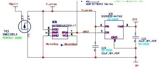
6. The lower area of the PCB includes a low-bias linear power supply with reverse current protection to prevent current from the debug lead flowing into the battery. It also has a Lithium cell under voltage protection and reverse connection protection. The reverse protection is provided by a P-channel MOSFET to form a super low drop pseudo diode.

Conclusion;
4. The LoRa RF signal is routed by cable to the Bead 868MHz aerial made by RF Solutions. Please note that I have placed many vias coupling 0V planes on 3 of the four PCB copper layers.
- The board is higher density 4 layers 90mm x 45mm whereas the previous board was double-sided (100x52mm) giving a safer larger 0V plane area for the aerials that has proven to be unnecessary. The design has three radios; LoiRaWAN 868MHz, Bluetooth and GNSS. Plus NFC is provided by a Coilcraft wound coil mounted on the pins on the bottom left side of the board and facing to the left of the unit.
- The top and bottom have 0V planes with very many vias plus a 0V internal plane and a 3.3V internal plane has some tracks.
Battery protection + SII S13R1 series
LDO regulator has a bias current of <9uA
6. The lower area of the PCB includes a low-bias linear power supply with reverse current protection to prevent current from the debug lead flowing into the battery. It also has a Lithium cell under voltage protection and reverse connection protection. The reverse protection is provided by a P-channel MOSFET to form a super low drop pseudo diode.
GNSS power supply is separated from the
main power supply. This is so that the main
power supply remains relatively free of dips
when the GNSS is switched on.
Explanation of LoRa;
The links below are good explanations of LoRa spread spectrum modulation. There are other types of spread spectrum such as frequency hopping.
During the time of this project, we received excellent support from various manufacturers although the support on the wireless side was difficult to obtain at first. The UK PCB assemblers and makers were good we used Wilson Process Systems which did everything including working around my mistake without me needing to use a soldering iron. For some other work, a Chinese maker was very good, evidently guessing the answers to questions correctly.
Although the CAD tools CADSTAR 17 and 18 used were new they had some very out-of-date footprints with the location incorrectly placed on pin one rather than in the centre of the footprint as it should have been since the 1990s. This fault was difficult to find though easy to correct if found before PCBs had been made. On the other hand, CADSTAR is one of the easier CAD tools to start using or to put aside and start using again but at least one stay away at a training course is worth buying.
Bluetooth Lamb collar;
This started to be developed although something was going to be available - Like the unit above it could be powered and interrogated using an NFC link. So if either unit were found with a dead battery not all is lost. The purpose of the lamp Bluetooth was to associate lambs with their parent ewe, thereby maintaining breeding records without the cost of a DNA test.
With care, UHF and microwave radio have turned out not to be as frightening as I had thought to work with. This board went through several reviews and advice was sought and taken resulting in the board working the first time. There are some changes to carry out they are not urgent but for a connector part number mistake in the BoM. The requirement did change and so there were earlier boards purchased and designed.
I am told of and I have seen examples of PCB designs where the same care has not been taken, such designs perform poorly. All design work needs care to be taken then you can expect very good outcomes.
I am told of and I have seen examples of PCB designs where the same care has not been taken, such designs perform poorly. All design work needs care to be taken then you can expect very good outcomes.
No comments:
Post a Comment